VACUUBRAND PC 620 NT plastic housing User Manual
Page 101
page 101 of 113
➨
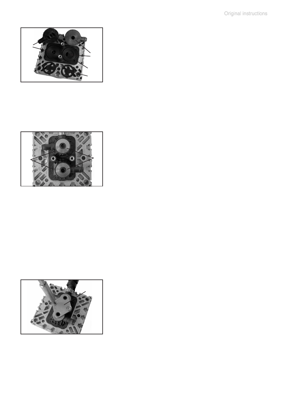
Insert O-rings (M) and valves (N). See fig-
ure for the correct position of the valves:
+
Inlet side (IN):
Marked ”IN” next to the valve seat. The
valve tongue points at the kidney-shaped
orifice in the valve seat.
+
Outlet side (EX):
Marked with ”EX” next to the valve seat. The
valve is oriented the same direction as the
valve at the inlet side.
EX
IN
➨
Position valve heads (O), with connection
tube or connection fastener (Q), and disc
springs (R) on the valve seats. Position disc
springs with large opening downwards. Pay
attention to the correct orientation of the
valve heads.
+
Center the valve head with respect to the
valve seat. The valve head must lie flat on
the valve seat.
M
N
O
R
➨
Position clamping bracket (S) with counter-
sunk bores facing upwards.
➨
Align the countersunk bores with the thread-
ed pegs.
➨
Loosely fasten the countersunk screws and
correct the alignment of the valve heads if
necessary.
➨
Tighten countersunk screws with Torx screwdriver T20.
+
Torque: 2.2 ft
.
lb
f
(3 Nm).
Valve head with gas ballast connection:
➨
Insert square nut (K) in the groove of the head cover (J) or position
square nut in the groove and then screw on connection fastener.
+
Loosely fasten fillister head screw (L).
S