Carrier AIR COOLED SPLIT SYSTEM 38AQS008 User Manual
Page 9
2
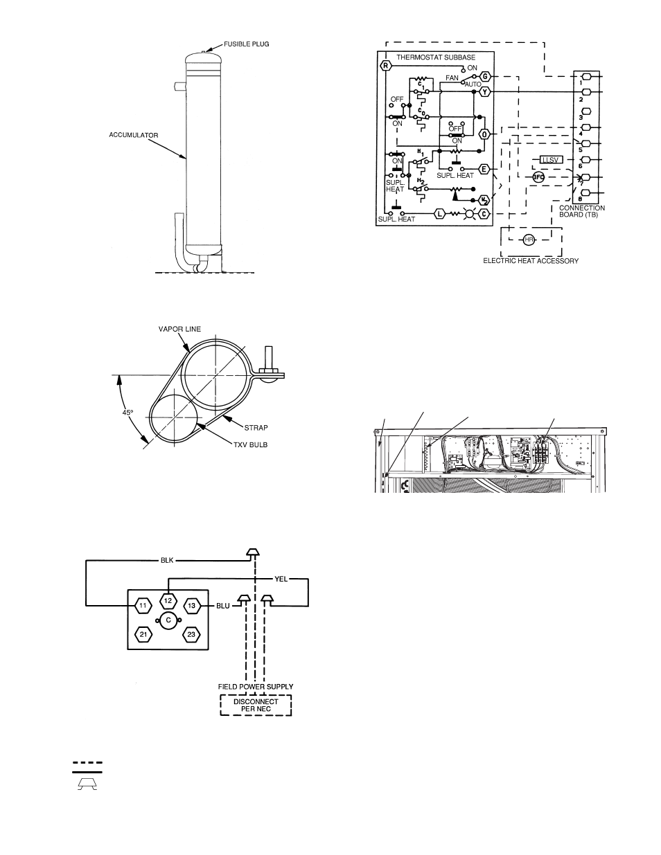
CORNER
POST
RACEWAY
THERMOSTAT
FIELD CONNECTION
POWER WIRING
CONNECTIONS
Fig. 6 — Fusible Plug Locations
LEGEND
NOTE: The 8 o’clock position is shown above.
Fig. 7 — TXV Sensing Bulb Location
TXV —
Thermostatic Expansion Valve
LEGEND
Fig. 8 — 38AQS008 Power Wiring Connections
C
—
Contactor
NEC —
National Electrical Code (U.S.A.)
Field Wiring
Factory Wiring
Splice Connection (Factory Supplied)
LEGEND
Fig. 9 — Control Wiring Connections
C
— Cooling
LLSV — Liquid Line Solenoid
Valve
H
— Heating
HR — Heater Relay
SUPL — Supplemental
IFC — Indoor Fan Contactor
TB
— Terminal Block
Fig. 10 — Field Control Wiring Raceway
→
9
801
See also other documents in the category Carrier Pumps:
- SYNERGY 38YD (9 pages)
- 38YCX (8 pages)
- 50TFQ008-012 (56 pages)
- INFINITY 50XT-A (4 pages)
- 38QN (8 pages)
- 50CR (32 pages)
- 542D060 (18 pages)
- 50LJQ008 (24 pages)
- 38HQ (20 pages)
- XPOWER 38VYX130 (14 pages)
- 38E (20 pages)
- AQUAZONE PTV (64 pages)
- AQUAZONE 50PCH (52 pages)
- 38QP024 (6 pages)
- 38BYC (8 pages)
- XPOWER 38VYX050 (14 pages)
- AQUAZONE 50QE900-250FS (8 pages)
- AQUAZONE RDS006-060 (44 pages)
- 50YX (20 pages)
- 50VQ (14 pages)
- 50HQ (14 pages)
- 50MQ (12 pages)
- 10 SEER SPLIT-SYSTEM 38YCW (8 pages)
- 38AUQ (36 pages)
- WEATHERMASTER 2000 (9 pages)
- COMFORT 25HCS (6 pages)
- 50DQ (6 pages)
- 38AC (6 pages)
- 50RTG (28 pages)
- AQUAZONE 50RTP03-20 (60 pages)
- COMFORT 50EZ-A (6 pages)
- 38AYB (4 pages)
- 50YQ (16 pages)
- 50ET (14 pages)
- COMFORT SERIES 25HCB3 (8 pages)
- 38QF (18 pages)
- WEATHERMASTER III 38HQ (19 pages)
- GT-PX (56 pages)
- 50QQ (16 pages)
- AQUAZONE 50VQP084-300 (48 pages)
- 50JS (4 pages)
- 50JS (28 pages)
- 38AQ024 (14 pages)
- 38QB (20 pages)