Step 2 — rig and mount the unit, Step 3 — complete refrigerant piping connec- tions – Carrier AIR COOLED SPLIT SYSTEM 38AQS008 User Manual
Page 2
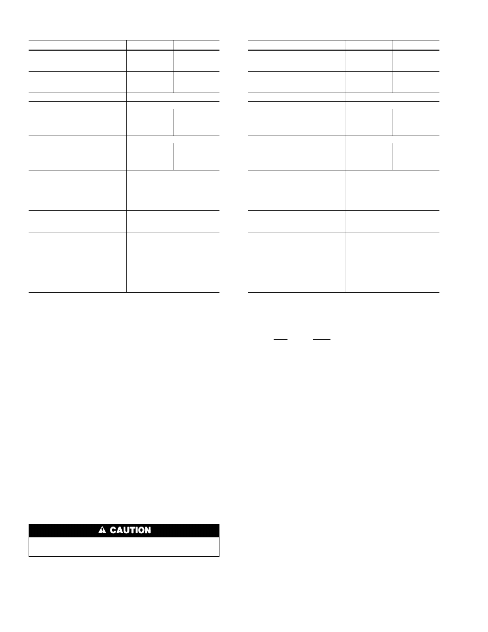
Table 1A — Physical Data (English)
UNIT 38AQS008
60 Hz
50 Hz
OPERATING WEIGHT (lb)
Aluminum Coils (Standard)
540
594
Copper Coils (Optional)
608
662
RIGGING WEIGHT (lb)
Aluminum Coils (Standard)
590
644
Copper Coils (Optional)
658
712
REFRIGERANT*
R-22
COMPRESSOR
Reciprocating, Semi-Hermetic
Quantity...Type
1...06DA818
1...06DA824
Quantity Cylinders
4
6
Speed (rpm)
1750
1460
Oil Charge (oz) (ea)
88
128
OUTDOOR FAN
Propeller; Direct Drive
Quantity...rpm
1...1100
1...960
Diameter (in.)
26
26
Motor Hp (NEMA)
3
⁄
4
1
⁄
3
Nominal Airflow (cfm)
6500
6100
OUTDOOR COIL
Enhanced Copper Tubes,
Aluminum Lanced Fins
Face Area (sq ft)
18.0
Storage Capacity (lb)†
16.56
Fins/in.
17.0
Rows (No.)
2
CONNECTIONS (Sweat)
Suction (in.)
1
1
⁄
8
Liquid (in.)
1
⁄
2
CONTROLS
Pressurestat Settings (psig)
High Cutout
426
Ϯ 7
Cut-in
320
Ϯ 20
Low Cutout
7
Ϯ 3
Cut-in
22
Ϯ 5
Defrost Thermostat
Initiate Defrost (F)
28
Terminates Defrost (F)
65
LEGEND
NEMA — National Electrical Manufacturing Association (U.S.A.)
*Unit is factory supplied with holding charge only.
†Storage capacity of coil with coil 80% full of liquid R-22 at 120 F.
Table 1B — Physical Data (SI)
UNIT 38AQS008
60 Hz
50 Hz
OPERATING WEIGHT (kg)
Aluminum Coils (Standard)
245
270
Copper Coils (Optional)
276
299
RIGGING WEIGHT (kg)
Aluminum Coils (Standard)
268
292
Copper Coils (Optional)
298
323
REFRIGERANT*
R-22
COMPRESSOR
Reciprocating. Semi-Hermetic
Quantity...Type
1...06DA818
1...06DA824
Quantity Cylinders
4
6
Speed (r/s)
29.2
24.2
Oil Charge (L) (ea)
2.60
3.78
OUTDOOR FAN
Propeller; Direct Drive
Quantity...r/s
1...18.3
1...16.0
Diameter (mm)
660
660
Motor Hp (NEMA)
3
⁄
4
1
⁄
3
Nominal Airflow (L/s)
3070
2900
OUTDOOR COIL
Enhanced Copper Tubes,
Aluminum Lanced Fins
Face Area (m
2
)
1.67
Storage Capacity (kg)†
7.5
Fins/m
669
Rows (No.)
2
CONNECTIONS (Sweat)**
Suction (in.)
1
1
⁄
8
Liquid (in.)
1
⁄
2
CONTROLS
Pressurestat Settings (kPa)
High Cutout
2937
Ϯ 48
Cut-in
2206
Ϯ 138
Low Cutout
48
Ϯ 20
Cut-in
151
Ϯ 34
Defrost Thermostat
Initiate Defrost (C)
−2.2
Terminates Defrost (C)
18.3
LEGEND
NEMA — National Electrical Manufacturing Association (U.S.A.)
*Unit is factory supplied with holding charge only.
†Storage capacity of coil with coil 80% full of liquid R-22 at 49 C.
**All pipe sizes are OD inches; equivalent sizes in millimeters follow:
in.
mm
1
⁄
2
12.7
1
1
⁄
8
28.6
CONSIDER SYSTEM REQUIREMENTS
• Consult local building codes and NEC (U.S.A.) for spe-
cial installation requirements.
• Allow sufficient space for airflow clearance, wiring, re-
frigerant piping, and servicing unit. See Fig. 2.
• Locate unit so that outdoor unit airflow is unrestricted on
all sides and above. Refer to Fig. 2.
• Unit may be mounted on a level pad directly on base rails
or mounted on raised pads at support points. See Fig. 2 for
weight distribution based on recommended support points.
• Provide for condensate drainage and defrost water dis-
posal beneath unit.
• Areas with high snowfall may need elevated mounting for
adequate airflow.
NOTE: If vibration isolators are required for a particular in-
stallation, use corner weight information in Fig. 2 to make
proper selection.
Step 2 — Rig and Mount the Unit
Be sure unit panels are securely in place prior to
rigging.
RIGGING — These units are designed for overhead rig-
ging. Refer to rigging label for preferred rigging method.
Spreader bars are not required if top crating is left on unit.
All panels must be in place when rigging. (See Fig. 3.) As
further protection for coil faces, plywood sheets may be placed
against sides of unit, behind cables. Run cables to a central
suspension point so that angle from the horizontal plane is
not less than 45 degrees. Raise and set unit down carefully.
If it is necessary to roll unit into position, mount unit on
rails, using a minimum of 3 rollers. Apply force to rails, not
unit. If unit is to be skidded into position, place it on a large
pad and drag it by the pad. Do not apply any force to unit.
Raise from above to lift unit from rails or pad when unit
is in final position.
After unit is in position, remove all shipping wrapping and
top crating.
MOUNTING — The unit must be elevated to ensure drain-
age from basepan during sub-freezing conditions and to pre-
vent or limit blockage of outdoor coil during snowfall. Con-
sideration should be given to specific geographical areas when
determining height of unit elevation.
COMPRESSOR MOUNTING — As shipped, compressors
are held down by 4 bolts. After unit is installed, loosen each
bolt until the snubber washer can be moved with finger pres-
sure. See Fig. 4.
Step 3 — Complete Refrigerant Piping Connec-
tions —
Suction connection is sweat with plastic cap; liq-
uid connection is sweat with plastic cap. Refer to Table 2 for
the proper line sizes. Follow standard piping practices.
2