Carrier AIR COOLED SPLIT SYSTEM 38AQS008 User Manual
Page 5
All field wiring must comply with NEC (U.S.A.) and lo-
cal requirements.
Install field wiring as follows:
1. Install conduit through side panel openings.
2. Install power lines to connections as shown in Fig. 8. Wrap
connections with electrical tape.
Voltage to compressor terminals during operation must be
within voltage range indicated on unit nameplate (also see
Table 4). Voltages between phases must be balanced within
2% and the current within 10%. Use the formula shown in
Table 4, Note 2, to determine the percent voltage imbalance.
Operation on improper line voltage or excessive phase im-
balance constitutes abuse and may cause damage to elec-
trical components. Such operation would invalidate any ap-
plicable Carrier warranty.
ACCESSORY ELECTRIC HEAT — If the system is to be
equipped with an accessory electric heater, refer to the
40RMQ008 installation instructions and Tables 5A and 5B.
FIELD CONTROL WIRING — Install a Carrier-approved
accessory thermostat assembly according to installation in-
structions included with the accessory. Locate thermostat as-
sembly on a solid wall in the conditioned space to sense av-
erage temperature in accordance with thermostat installation
instructions. Carrier-approved thermostat is Part Number
HH07AT-171. Subbase is HH93AZ-188.
Route thermostat cable or equivalent single leads of col-
ored wire from subbase terminals to low-voltage connec-
tions on unit (shown in Fig. 9) as described in Steps 1 through
3 below.
1. Connect thermostat wires to screw terminals of low-
voltage connection board.
2. Pass the control wires through the hole provided in the
corner post. (See Fig. 10.)
3. Feed wire through the raceway built into the corner post
to the 24-v barriers located on the left side of the control
box. The raceway provides the required clearance be-
tween the high- and low-voltage wiring.
NOTE: 39 VA is available for field-installed accessories.
Control power requirement for heat pump outdoor unit is
36 VA (sealed). The factory-supplied control transformer is
75 VA.
NOTE: For wire runs, use the following insulated wire:
LENGTH
INSULATION
RATING (C)
SIZE
Ft
M
AWG
sq mm
0-50
0-15.2
35
18
0.82
50-75
15.2-22.9
35
16
1.30
Over 75
Over 22.9
35
14
2.08
LEGEND
AWG — American Wire Gage
All wire larger than no. 18 AWG (American Wire Gage)
cannot be directly connected to the thermostat and will re-
quire a junction box and splice at the thermostat.
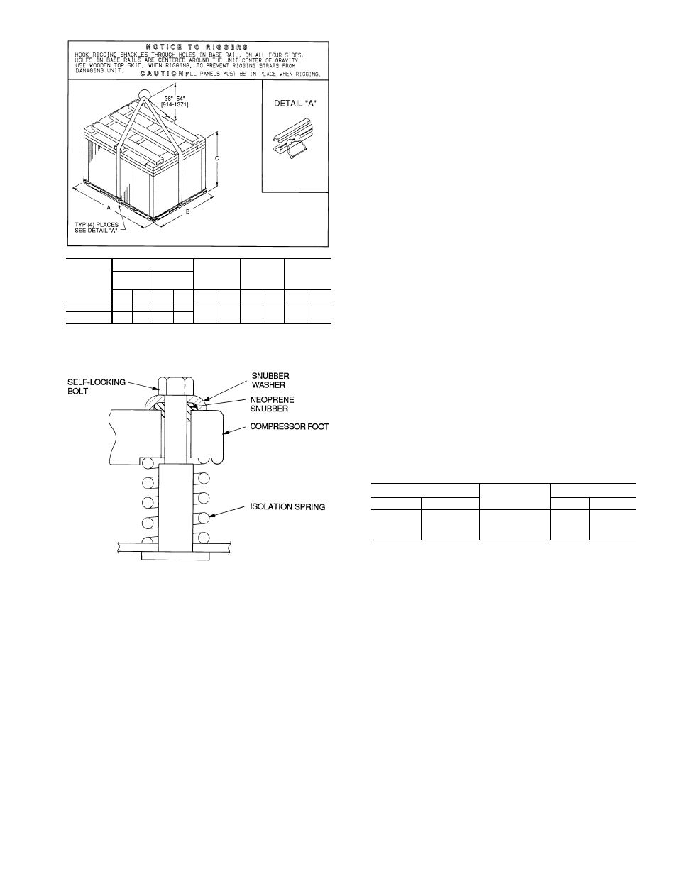
UNIT
38AQS008
MAX WEIGHT
A
B
C
w/Al
Coil
w/Cu
Coil
Lb
Kg
Lb
Kg
in.
mm
in.
mm
in.
mm
60 Hz
590
268
658
298
45.0
1143
38.5
989
43.5
1105
50 Hz
644
292
712
323
Fig. 3 — Rigging Label
Fig. 4 — Compressor Mounting
5