Step 4 — make electrical connections – Carrier AIR COOLED SPLIT SYSTEM 38AQS008 User Manual
Page 3
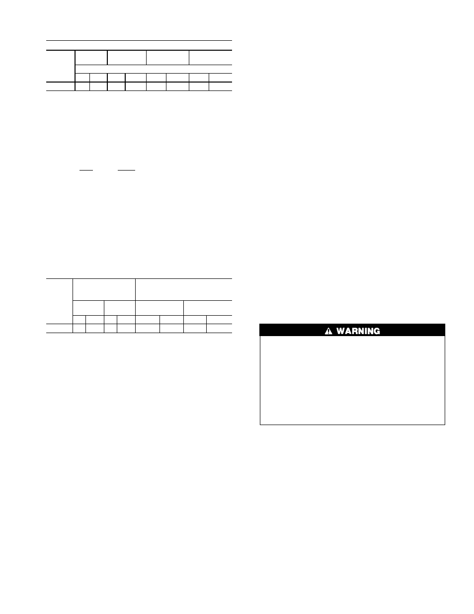
Table 2 — Refrigerant Piping Sizes
LINEAR LENGTH OF PIPING — ft (m)
UNIT
38AQS
0-25
(0-7.6)
25-50
(7.6-15.2)
50-75
(15.2-22.9)
75-100
(22.9-30.5)
Line Size (in. OD)
L
S
L
S
L
S
L
S
008
1
⁄
2
1
1
⁄
8
5
⁄
8
1
1
⁄
8
5
⁄
8
1
1
⁄
8
5
⁄
8
1
1
⁄
8
LEGEND
L — Liquid Line
OD — Outside Diameter
S — Suction Line
NOTES:
1. Pipe sizes are based on a 2° F (1° C) loss for liquid and suction
lines.
2. Pipe sizes are based on the maximum linear length shown for each
column, plus a 50% allowance for fittings.
3. Charge units with R-22 in accordance with unit installation
instructions.
4. Line size conversion to mm is:
in.
mm
1
⁄
2
12.7
5
⁄
8
15.9
3
⁄
4
19
1
1
⁄
8
28.6
1
3
⁄
8
34.9
SIZE REFRIGERANT LINES — Consider length of piping
required between 38AQS unit and 40RMQ unit, amount of
liquid lift, and compressor oil return. See Table 3 and also
refer to Part 3 of Carrier System Design Manual for design
details and line sizing. Refer to 40RMQ installation instruc-
tions for additional information.
Table 3 — Liquid Line Data
UNIT
38AQS
MAX
ALLOWABLE
LIQUID LIFT
LIQUID LINE
Heating
Cooling
Max Allowable
Pressure Drop
Max Allowable
Temp Loss
ft
m
ft
m
psi
kPa
F
C
008
75
22.9
65
19.8
7
48
2
1
1. The liquid lift in cooling mode is based on 80/67 F (22.7/19.4 C)
(db/wb [dry bulb/wet bulb]) entering indoor-air temperature and a
95 F (35 C) outdoor-air temperature, with R-22 refrigerant, at an
indoor airflow of 3000 cfm (1416 L/s).
2. The liquid lift in heating mode is based on 70/60 F (21.1/15.6 C)
(db/wb) entering indoor-air temperature and a 47/43 F (8.3/6.1 C)
(db/wb) outdoor-air temperature, with R-22 refrigerant, at an in-
door airflow of 3000 cfm (1416 L/s).
FILTER DRIER AND MOISTURE INDICATOR — See
Fig. 5. The filter drier is factory supplied and field-installed
in the liquid line. Moisture indicator is field-supplied and
should be installed just after liquid line shutoff valve. Do not
use a receiver; there is none provided with unit and one should
not be used.
NOTE: Unit is shipped with R-22 holding charge. System
pressure must be relieved before removing caps. Recover re-
frigerant prior to brazing.
Pass nitrogen or other inert gas through piping while braz-
ing to prevent formation of copper oxide.
LIQUID LINE SOLENOID VALVE — A field supplied liq-
uid line solenoid valve (LLSV) is recommended when pip-
ing system length exceeds 75 ft (23 m). The LLSV must be
of the biflow type, suited for use in heat pump systems.
NOTE: Carrier recommends part number EF23JS214 (Sporlan
model CB14S2,
5
⁄
8
-in. ODF/
7
⁄
8
-in. ODM) available from the
Replacement Components Division of Carrier Corporation.
This solenoid requires field supplied Sporlan MKC-2 coils.
Wire the solenoid in parallel with the compressor con-
tactor coil.
Install the LLSV near the outdoor unit. The flow arrow
must be pointed toward the outdoor unit.
SAFETY RELIEF — A fusible plug is located on top of the
accumulator. See Fig. 6. Note that all safety relief compo-
nents are factory installed. Do not cap fusible plug. If local
code requires additional safety device(s), install as directed.
SUCTION PIPING AT INDOOR COIL AND TXV SENS-
ING BULB LOCATION — To achieve good mixing of re-
frigerant leaving the indoor coil suction header for proper
sensing by the thermostatic expansion valve (TXV) bulb (see
Fig. 7):
1. A minimum of two 90-degree elbows should be installed
upstream of the TXV bulb location.
2. The TXV bulb should be located on a vertical riser where
possible. If a horizontal location is necessary, secure the
bulb at approximately the 4 o’clock position or the
8 o’clock position. See Fig. 7.
3. Enter suction pipe sizing charts in the Carrier System De-
sign Manual at design tons and equivalent length for
2° F (1° C) loss. If the reading falls between 2 sizes on
the chart, choose the smaller pipe size.
4. Make sure that the piping system has no inherent oil traps,
and the piping layout will not allow oil to migrate into an
idle evaporator coil.
5. Complete refrigerant piping from indoor coil to outdoor
coil before opening liquid and suction lines at the 38AQS
unit. See Tables 1A, 1B, and 2 for piping selection data.
Step 4 — Make Electrical Connections
Unit cabinet must have an uninterrupted, unbroken elec-
trical ground to minimize the possibility of personal in-
jury if an electrical fault should occur. This ground may
consist of electrical wire connected to unit ground lug
in control compartment, or conduit approved for elec-
trical ground when installed in accordance with NEC
ANSI (American National Standards Institute, U.S.A.)/
NFPA (National Fire Protection Association, U.S.A.) 70
and local electrical codes. Failure to follow this warn-
ing could result in the installer being liable for personal
injury of others.
FIELD POWER SUPPLY — All units except 208/230-v
(60 Hz) units are factory wired for the voltage shown on the
nameplate. If the 208/230-v unit is to be connected to a 208-v
power supply, the transformer must be rewired by moving
the black wire from the 230-v orange wire on the trans-
former and connecting it to the 208-v red wire from the trans-
former. The end of the orange wire must then be
insulated.
Refer to unit label diagram for additional information. Short
wire leads (pigtails) are provided for field wire connections.
Use factory-supplied splices or UL approved copper/
aluminum connector.
When installing units, provide a disconnect per NEC
(U.S.A.).
3
399
→