Twin City Inline Fume Exhaust Fans - IM-1080 User Manual
Page 3
Twin City Fan IM-1080
3
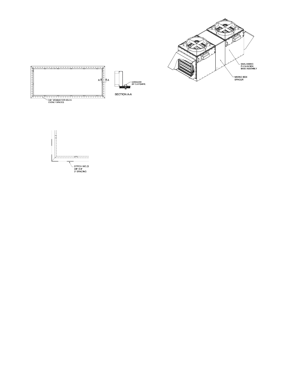
Figure 4. Mixing Box
Roof Curb Installation
Caution: Roof curbs should be square and level to ensure
safe fan installation and proper sealing of gas stream to
the fan.
Roof curbs shall be installed and fully attached to struc-
tural support (by others) which is typically steel or concrete
using 1/2" diameter bolts w/ 1-3/8" washers (by others)
For attachment to structural steel the curb can be con-
tinuously welded or stitch welded using 3/8" x 6" welds
with a maximum of 3" spacing between welds. Welds
should be evenly spaced along curb side and corners
Mixing Plenum Box Assembly and Installation
The modular plenum mixing boxes are designed to allow
for easy installation and future expandability. Single mixing
plenum boxes are fully assembled (less any dampers) to
expedite installation. Depending on the size, multi-unit mix-
ing boxes may or may not be assembled. When installing
the mixing box(es), it is important to follow the guidelines
for lifting and rigging on page 2.
When a single-unit mixing plenum box is installed, prepare
the roof curb or mounting structure. Lay gasket material
on the top edge of the roof curb. Lift mixing box onto
curb and square (level) mixing box.
Depending on the air intake (side or bottom), the mixing
box must be oriented to allow for direct duct connection
into the mixing plenum box. Match drill roof curb to mix-
ing plenum box. Attach mixing plenum box to curb using
1/2” diameter bolts with 1 3/8” washers (by others).
For multi-unit configurations, some assembly may be
required. There are at least two different assemblies in a
multi-unit configuration. There is the mixing plenum box
assembly and the mixing box spacer. See figure 4. There
will be one less spacer than the quantity of mixing plenum
boxes.
To assemble, space the mixing boxes a distance apart that
is slightly more than the width of the spacer section. Utilize
a gasket between the mixing box and the spacer section
to provide a tight seal.
Install 316 stainless steel bolts to attach the spacer and
the mixing box. Repeat as necessary for each section.
When the multi-unit mixing plenum box is assembled, rig
the mixing box system into place in accordance with
Figure 1 to avoid any damage.
Install mixing plenum box assembly onto a prepared (gas-
ket material on mating surface) roof curb or mounting
structure. Lay Square (level) mixing box. Install lag bolts
into the mixing plenum box to roof curb as indicated.
Fan and Windband Installation
•
Follow proper handling instructions as provided earlier.
•
Identify each fan and component and match the equip-
ment up with the supplied customer drawing(s).
•
Move the fan to the final mounting location.
•
Remove skid, crates and packing materials carefully.
•
For fans mounted directly to roof curb (supplied with a
curb cap), place the fan on properly installed roof curb.
Fans mounted on a mixing plenum box (supplied with
mixing plenum box transition) require the installation of
the mixing plenum box prior to installing fan.
•
Fans shipped as a single unit shall be broken down
into several parts. Install each item individually in the
following order:
1. Fan and curb cap onto the installed roof curb
-or-
Fan and mixing plenum box transition onto in-
stalled mixing box.
2. Stack extension, if in the scope of supply (TFE/
QFE Only)
3. Windband
Note: When installing the components, lifting lugs shall be uti-
lized for safe installation. Lifting lugs are designed for the weight
of the component they are welded to and should not be used
to lift assemblies.
Fan Housing Installation
1. Place supplied gasket around the perimeter of the mix-
ing plenum box or roof curb.
2. Lower fan housing onto roof curb or mixing plenum box
aligning the bolt holes on the two components. Allow
for gasket to compress naturally prior to securing fan
housing to the adjacent component.
3. Install 316 stainless steel hardware (provided) in all
mounting holes. Use a commercially available anti-
seizing compound formulated for 316 stainless steel to
hardware. Carefully level the unit on the roof curb or
mixing plenum box. Be careful not to force the fan to
the mounting structure. This may cause misalignment
which may unsafe operating conditions, cause vibration
and premature failure.
4. Check the alignment of the bearings. Shim or reposition
the bearings if necessary.
5. Check face alignment of sheaves on belt driven fans.
Check tension of belts to see if it is sufficient. Sheaves
on belt driven fans are often provided with taperlock
bushings. When tightening bushing bolts, proceed in a
progressive manner to avoid cocking the tapered sur-
faces between the bushing and the sheave.
6. Check the tightness of the wheel on the shaft. Check
the tightness of foundation bolts, motor bolts, sheaves,
and bearings. Make sure there is no rubbing or binding
and that the wheel-inlet cone clearances and overlap
are correct.
Figure 2. Bolted Installation
Figure 3. Welded Installation