Bearing maintenance, Wheel and shaft maintenance, Structural maintenance – Twin City Heavy Duty Centrifugal Fans - ES-995 User Manual
Page 5: Duct connections, Optional accessories
5
Twin City Engineering Supplement ES-995
reinstall belts. Tighten sheave bolts (or setscrews if appropriate).
When replacing belts, replace the entire set. Never use belt
dressing on any belts.
Bearing Maintenance
Proper lubrication of the fan drive bearings helps assure maxi-
mum bearing life. All fans are equipped with decals indicating
relubrication intervals for normal operating conditions. Figures
5, 6, and 7 illustrate the lubrication schedules for ball bear-
ings, solid pillow block spherical roller bearings, and split pil-
low block spherical roller bearings, respectively. Note that all
speeds shown do not apply to all shaft sizes in that group.
Consult the factory if in doubt of maximum speed for a par-
ticular bearing. Note that every installation is different and the
frequency of relubrication should be adjusted accordingly.
On high moisture applications the lubrication frequency may
need to be doubled or tripled to adequately protect the bear-
ings. Double the relubrication frequency on fans with vertical
shafts.
Observation of the conditions of the grease expelled from
unit ball or roller bearings at the time of relubrication is the
best guide as to whether regreasing intervals and amount of
grease added should be altered. Spherical roller bearings with
split pillow block housings should be lubricated until grease
purges or overheating may result. Follow the lubrication interval
and amount noted in Figure 7. Spherical roller bearings with
split pillow block housings should be serviced once per year.
Remove cap, clean out old grease and replace by filling the
bottom half of the housing 1/3 full.
Greases are made with different bases. There are synthetic
base greases, lithium base, sodium base, etc. Avoid mixing
greases with different bases. They could be incompatible and
result in rapid deterioration or breakdown of the grease. The
lubrication sticker identifies a list of acceptable lubricants. All
bearings are filled with a lithium-based grease before leaving
the factory. When the fans are started, the bearings may dis-
charge excess grease through the seals for a short period of
time. Do not replace the initial discharge because leakage will
cease when the excess grease has worked out. Sometimes
the bearings have a tendency to run hotter during this period.
This is no reason for alarm unless it lasts over 48 hours or
gets very hot (over 200°F). When relubricating, use a sufficient
amount of grease to purge the seals. Rotate bearings by hand
during relubrication.
Wheel and Shaft Maintenance
Periodically inspect the shaft and wheel for dirt buildup, corro-
sion, and signs of excess stress or fatigue. Clean the compo-
nents. If the wheel is removed for any reason, make sure that
it is securely attached to the shaft before restarting the fan.
Structural Maintenance
All structural components or devices used to support or attach
the fan to a structure should be checked at regular intervals.
Vibration isolators, bolts, foundations, etc., are all subject to
failure from corrosion, erosion, and other causes. Improper
mounting can lead to poor operation characteristics or fan
fatigue and failure. Check metallic components for corrosion,
cracks, or other signs of stress. Concrete should be checked
to insure the structural integrity of the foundation.
Duct Connections
The fan support structure is normally not designed to carry
loads imposed by the weight of ducts, silencers, stacks, etc.
Supporting these loads on the fan can cause housing distor-
tion and may cause performance problems due to the rela-
tion of fan housing to wheel. Use of flexible connections is
recommended when using vibration isolation or handling high
temperature gases.
Optional Accessories
1.
Turning Gear — A turning gear is sometimes used in
high temperature applications where the fan is exposed
to high temperature gases while not operating. The wheel
and shaft can expand unevenly due to the temperature
when sitting idle, which can cause vibration at startup
and/or a permanent set to the rotor. The turning gear
slowly turns the fan from the outboard side while it is not
operating, providing for even thermal expansion. It starts
automatically when the fan shuts down and disengages
automatically when the fan starts up again. More specific
information will be provided for each application.
2.
Shaft Seals — The standard shaft seal is a ceramic fiber
element retained with an aluminum retaining plate and
clips. Other configurations of shaft seals are available for
special applications, such as when it is necessary to keep
the shaft seal as gas tight as possible. Shaft seal appli-
cation manuals are provided in Engineering Supplement
ES-595.
3.
Variable Inlet Vanes — Variable inlet vanes are provided
as assemblies internally in the inlet cone or externally in
a flanged cylinder. The vanes are used to control volume
and save power in installations where different volumetric
operating conditions are used. Installation manuals are
provided in other engineering supplements for specific fan
types. Variable inlet vanes may be provided with powered
operators in which case the manufacturer’s installation and
operating manuals will be provided.
4.
Inlet Box and Inlet Box Dampers — Inlet boxes may be
provided to allow transition from a duct to the fan inlet.
Inlet box dampers may also be provided for volumetric
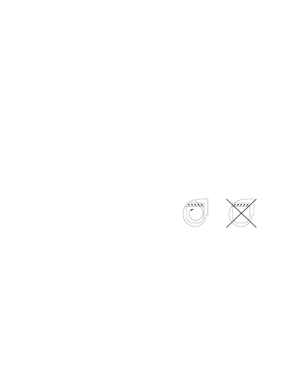
regulation similar to inlet vanes. Dampers are usually
provided as a complete assembly and are installed with
the damper axles parallel to the fan shaft. They should
be installed to pre-spin the air in the direction of fan
rotation. See Figure 3. Damage may occur if the fan is
operated regularly with damper settings less than 30%
open. Operation below 30% should be limited to start-up
or occasional periods of low duration.
Figure 3. Orientation of Damper Blades As Related
to Fan Rotation
5. Outlet Dampers — Outlet dampers are usually provided
completely assembled like the inlet dampers. The damper
is bolted to the fan discharge for volume control.
6.
Shaft Cooler — Also referred to as “heat slingers” or
“cooling wheels,” these are small, radially bladed aluminum
wheels that are split and bolted for installation between the
inboard bearing and fan housing. The backplate usually is
closest to the fan housing and the blades face the bear-
ing. Specific instructions will be provided by application.
7.
Oil Circulating Systems — Usually the following modifica-
tions will have to be made to the bearing if an oil circulat-
ing system is used.
a. Four drain holes will be drilled in the bearing, two on
each side of the bearing. Because of this, the bearing
may be drained from either side. (Drain from both holes
on one side of the bearing.)
b. It is not necessary to drain the bearing.
c. The bearing will be packed with grease to prevent corro-
sion until installed and started up. The drain holes will be
plugged with plastic covers to make sure they are open.
The customer MUST REMOVE most of the grease using
solvent and remove the plastic covers prior to starting
the oil circulating system.
d. A wet sump will be added in case of circulating oil
pump failure. Seals will be provided to accommodate the
RIGHT
WRONG