Top Flite S.E.5A User Manual
Page 7
of formers F-14A • F-17. All stringers are to be glued in "diamond-fashion "
This was done to get sharp impressions on the covering, like the real S. E 5A
had, and yet have stringers big enough not to warp after covering Glue in the rest
of the stringers, observing that they are alternately long and short (see Figure 6).
When dry, cut back short stringers level with rear of F-16 Carve and sand tail block
to conform to fuselage shape
Shape the headrest block provided to section, and tack-glue in position so it won't
get lost.
18. Glue R-l and R.2 together, also R-4 and R-5. Glue F-10 (ply) on front of F-8,
screw nylon brackets for upper cowl fastening onto F-10 and F-4: see fuselage side
view for positions
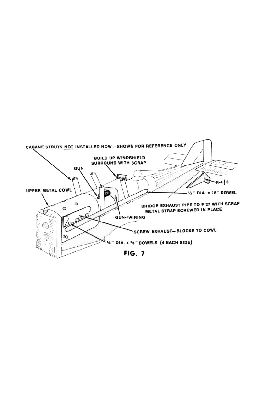
19. Screw upper and lower metal cowls onto fuselage Shape and sand nose
block to correct contours and add dummy radiator-cap (made from scrap) Drill
upper cowl tor needle valve in required position by temporarily installing engine.
While upper cowl is removed from fuselage, shape cylinder fairings from blocks
provided, screw to upper cowl and finish making exhaust pipes from hardwood
dowels provided Figure 7 shows final appearance
20. Cut a suitable hole in upper fuselage decking and tack-glue Vickers gun in
position, then cut out stiff card gun-fairing to template on plan and glue in posi-
tion Build up windscreen, lightly tack-glue on fuselage Sand fin and rudder parts.
Hinge together with material provided.
21. The whole stabilizer assembly, and the underfin (R-4 and R-5) may now be
glued permanently to the fuselage Take care while installing these parts to get
them properly aligned Lightly tack-glue the fin in position on the fuselage. Glue
rudder horn to rudder
22 Screw rudder and elevator servos in place Make pushrods to rudder and
elevator and check radio for smooth and free action of control surfaces. Bear in
mind here, that the type of pushrods required will depend upon how much interior
cockpit detail you intend to incorporate If you want, as we did, a completely
furnished cockpit with instrument board, pilot, seat and all the rest of the details,
it obviously will not do to have two big pushrods running through the center of
the cockpit In the prototype models we used short lengths of nylon tubing with
metal wire cable inside, from the servo back as far as F-14. From here back the
pushrods became 3/8 sq in the normal way The nylon tubing section was fastened
to the cockpit sides where it is hardly noticeable
If it is not intended to incorporate a full cockpit layout, normal 1/8 sq pushrods
all the way from the servos to the tail end will be all that is needed.
6