Fig. 19 – Top Flite S.E.5A User Manual
Page 15
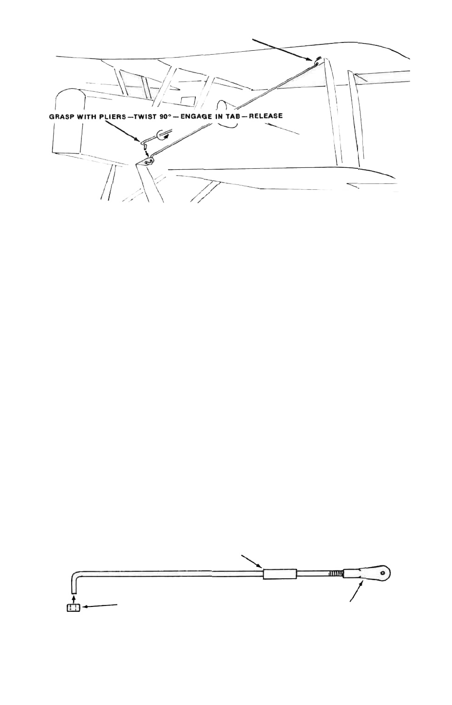
HOOK UPPER Z-BEND IN FIRST.
FIG. 19
TO DISASSEMBLE REVERSE INSTRUCTIONS
h Test the wire for tension When plucked the wire should feel taut
If the wire is slack this is no good and a new wire must be made—note
how much shorter it has to be If, on the other hand, the wire is
bent too short it cannot be engaged at all since it w i l l not reach the
second solder tab
i All of this might seem terribly difficult to get "just right" but we can
assure you that after making one or two mistakes, you will be making
almost all of the rest of the rigging wires "dead on" first time! Your
judgment quickly attunes to the requirements of the wire
With all the rigging wires in place on the model, a method of identifying
each wire must be seen to A good way is to color code each wire with a small
Jab of dope at one end Keep a list of the wires and the color-coding in your
flying field kit
AILERON CONNECTORS
These units are very simple Cut the tiny horns out of scrap 1/16" ply after
d r i l l i n g the 1/16" dia hole Make a small slit in the covering and glue the horns
in position—top of lower ailerons and bottom of upper ailerons
With the wings completely wire rigged, set the lower ailerons dead neutral,
using the links to adjust as necessary
Bend one end of the 9" long 1/16 wire supplied 1/4" from the end and a
90° angle Fasten this end to the lower aileron using a nylon button retainer to
keep it in place Hang a connecting link in the upper horn, cut the wires level
with each other and join with a short tube soldered in place See Figure 20.
Adjust the connecting link so the upper aileron is also at dead neutral
l a t e r , when trimming out the model in flight, each aileron can thus be adjusted
individually for the best result
TUBE
-NYLON BUTTON-RETAINER
ADJUSTING-LINK
FIG. 20
14