Top Flite S.E.5A User Manual
Page 14
make the rigging wires, which have to be added in any event, perform a real and
important function.
After all the dope on the model is completely dry, screw the lower wing in
place on the fus>elage. Snap the upper wing onto the cabane struts. Snap the four
interplane struts into the wings. The rigging wires are made from the 020" piano
wire supplied, and are called "flying" and "landing" wires — the "flying" wires
are the ones tensioned in flight, that is, the ones running from the fuselage up to
the upper wing the "landing" wires are the ones tensioned in a landing, that is,
the wires running from the top of the cabane struts down to the lower wing
As with the strut fastening method, we have given a good deal of attention
to figuring a simple and fast way to install the rigging wires. We did not want
to use turnbuckles. (the traditional method of getting the correct wire length)
because they are tiresome and must be reset every time the model is disassembled
for transportation
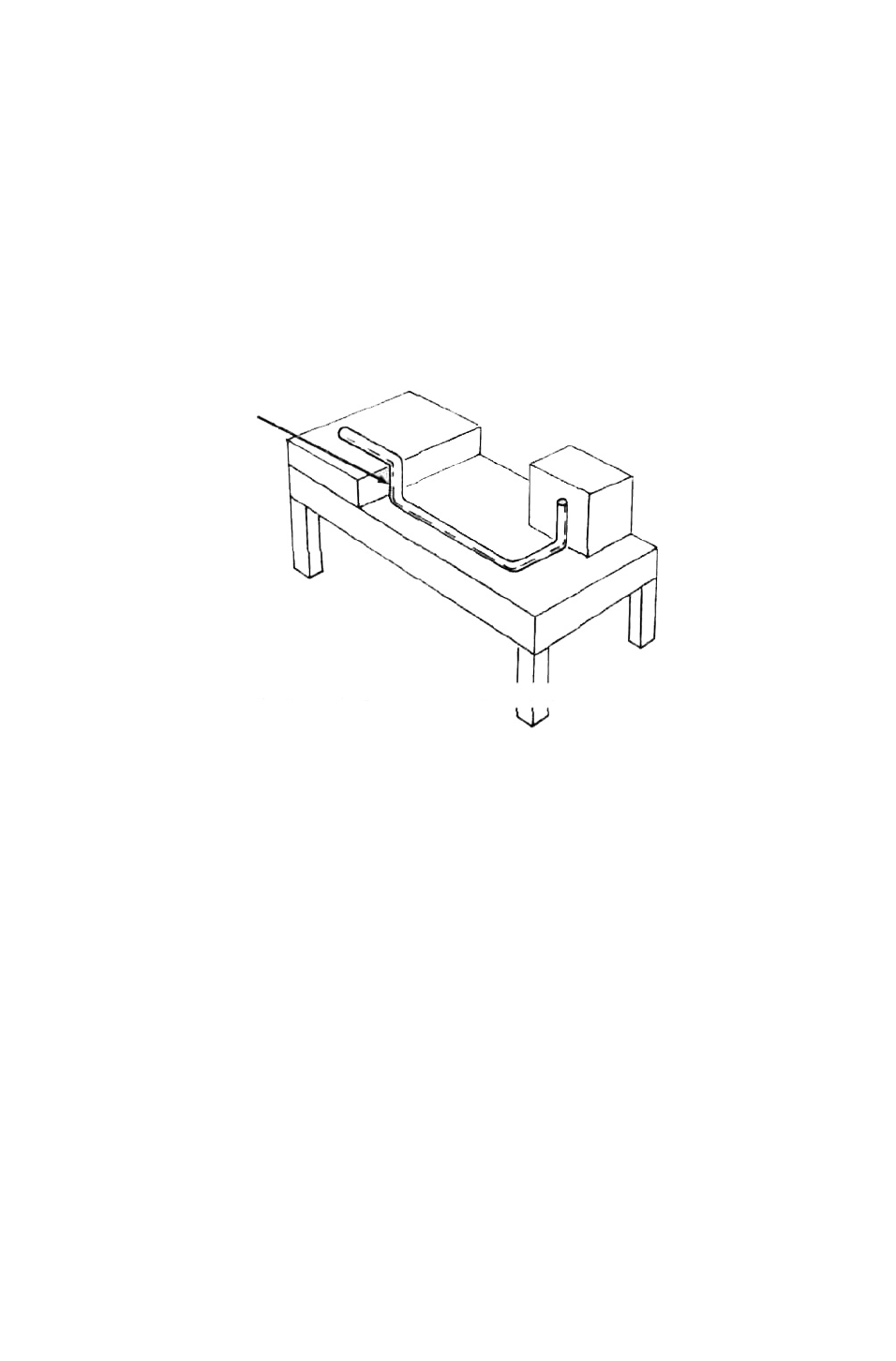
FIRST Z-BEND
FIG. 18
IMAGINARY "TABLE" AND "BLOCKS" DRAWN ONLY TO SHOW BEND DIRECTIONS
The method we have devised will take a little patience to bend the wires,
but once done, the wire length is set permanently, and the wires can all be re-
moved and replaced in seconds. Follow this method:
a Start by making the longest wires first. This way, if you accidentally
bend one too short the same piece can be used for a shorter wire later
on, saving waste. Work through to the shortest wires, doing these last.
b Leaving the wire the full 30" length, make a small normal Z-bend at
one end. See Figure 18.
c. Hook this Z-bend into the solder tab at the top of the front interplane
strut on the left side
d. Holding the wire in slight tension, make a mark on the wire (use a
felt-tip pen) where the wire passes the solder-tab at the top of the front
L. G. leg.
e Unhook the Z-bend. Bend the wire at the pen mark 90°. Now make
another 90° bend about 1/8" further along perpendicular to the long
straight section. Again, see Figure 18.
f. Cut off the wire about 1/8" along the new direction. The wire is now
made. Let's see if it fits o.k.
g See Figure 19. Hook the original Z-bend back into the tab it came
from. Now, by grasping the wire at the lower end with pliers and
twisting it, hook the other end into the second solder-tab. We are using
the torque in the wire to keep the bottom bend in the tab, and unless
the rigging wire is twisted the bottom bend cannot disengage. This
cannot happen in flight: however, removal is simply performed by
grasping the wire near the bottom with pliers and twisting until the
wire disengages.
13