Top Flite S.E.5A User Manual
Page 10
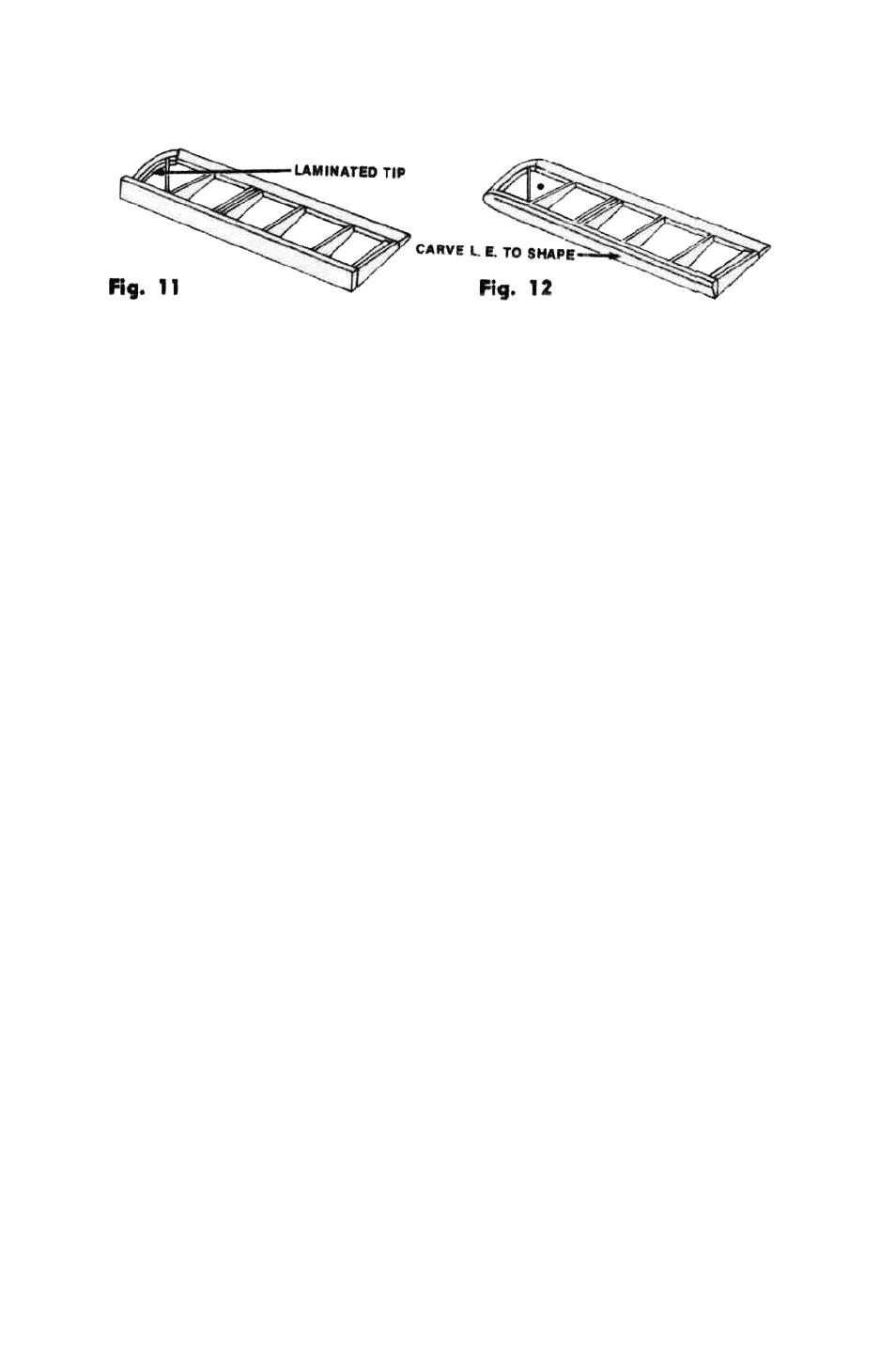
40. All four ailerons are identical—except of course that two are left and two
are right. Laminate each tip from two W-12 pieces. Construct flat on plan as in
Figure 11. When dry, carve and sand L. E. and tips to correct section: see Figure 12.
41. Hinge ailerons to bottom wing—see diagram on Plan Sheet 1. The hinges
should be held in place by toothpicks after drilling through wood and hinge material
together. Cut down the nylon aileron horns supplied to correct size indicated on
plan and glue between closely-spaced aileron ribs, using Titebond liberally to fill
holes in horn. Clamp and let dry.
42. Install nylon aileron bellcranks on W-12 (ply) bellcrank bearers. Connect
bellcranks and horns with supplied connecting links. Use small scrap of 1/16" sheet
to support covering where link exits from wing under surface.
43. Mount aileron servo in lower wing center section. It will be necessary to
make two right-angled brackets in most cases. For this purpose, two drilled metal
strips are provided which can be bent and re-drilled to suit the application. Con-
nect servo and bellcranks with 1/16" music wire pushrods, making the holes through
the ribs in the positions required by the equipment involved. Try to keep the holes
small—3/32" dia. is about right. Try out the ailerons using the radio, and do not
be satisfied with less than perfectly free and smooth movement over the whole
range of travel.
44. The top wing is made in three stages just as the lower wing, so detailed
instructions are not necessary. The only points of difference are in the slightly
altered rib-spacings, the lack of servo or bellcranks, and the center section which
is rather simpler.
When making the center-section, note that the 1/16" sheet covering extends from the
leading edge to the rear spar on the upper surface.
45. So far we have a complete fuselage and tail, with a lower wing which is
mounted in position and an upper wing not yet attached. The next job is to bring
these two items together to make a fairly complete S. E. 5A. This stage is a little
tricky, so work slowly and carefully. Study the drawing of the strut attachment
fittings on Plan Sheet 1. This nylon ball-and-socket joint is a new idea that we at
Top Flite have worked out to greatly simplify the traditionally difficult job of
rigging biplanes. This new system is far less demanding of super-accuracy than the
usual wire-bending methods. Also, assembly and dis-assembly is easier and quicker
and appearance much neater. (These fittings, incidentally, are available separately
packaged, and biplane builders will find them very useful—they will take up any
angle of strut attachment . . . sideways, backwards, forwards or combinations
of these. Ask your hobby dealer for Top Flite E-51 package).
46. From the 1/8" x 3/8" basswood strips supplied, cut 12 pieces 1-7/8" long. Drill
a 3/16" dia. hole in 8 of these 11/16" from one end and centered in the 3/8"
width. Glue these to the spars (on top of lower wing spars, and underneath upper
wing spars) so the drilled hole lines up with the first W-6 rib. Trim away ribs
and riblets slightly where required. Refer to full-size plans to check location.
The 4 undrilled pieces are glued to the forward spars in line with the drilled strips
already attached. These 4 strips will provide a covering-support for your left palm
when snapping the struts in place.
Next cut 4 pieces of 1/8" x 3/8" basswood 7/8" long, drill 3/16" in the center of each
piece and glue to the bottom of the spars in the lower wing at the dihedral-break,
again trim away ribs to suit.
9