Internal wiring diagram, Connections – Toa SR-TP12 User Manual
Page 10
10
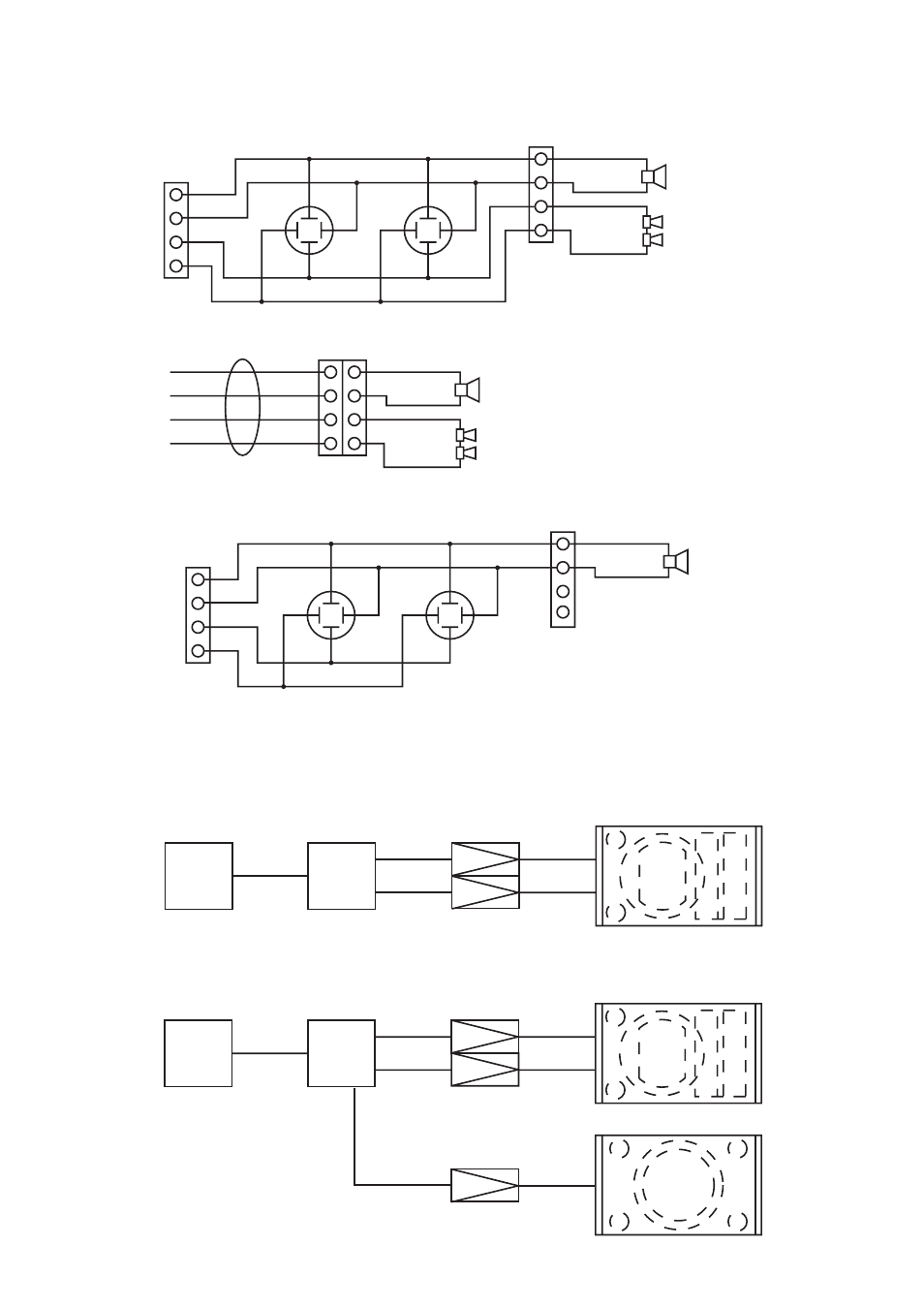
6. INTERNAL WIRING DIAGRAM
Figures below show the internal wirings of each speaker system.
2-
1+
1-
2+
LOW -
HIGH +
HIGH -
LOW +
2-
1+
1-
2+
HIGH +
HIGH -
Speaker cable
LOW +
LOW -
Red
White
Green
Black
SR-A12L, SR-A12S
SR-A12LWP, SR-A12SWP
2-
1+
1-
2+
INPUT -
THROUGH
THROUGH
INPUT +
2-
1+
1-
2+
SR-A18B
7. CONNECTIONS
System using the SR-A12L, SR-A12S, SR-A12LWP or SR-A12SWP
Mixer/Pre-amplifier
Digital Processor
Power Amplifier
LOW
SR-A12L, SR-A12S,
SR-A12LWP, SR-A12SWP
LOW
HIGH
HIGH
System which combines the SR-A12L or SR-A12S with the SR-A18B
SR-A12L, SR-A12S
SR-A18B
S-LOW
Mixer/Pre-amplifier
Digital Processor
Power Amplifier
LOW
LOW
HIGH
HIGH