Carrier 42 SERIES User Manual
Page 15
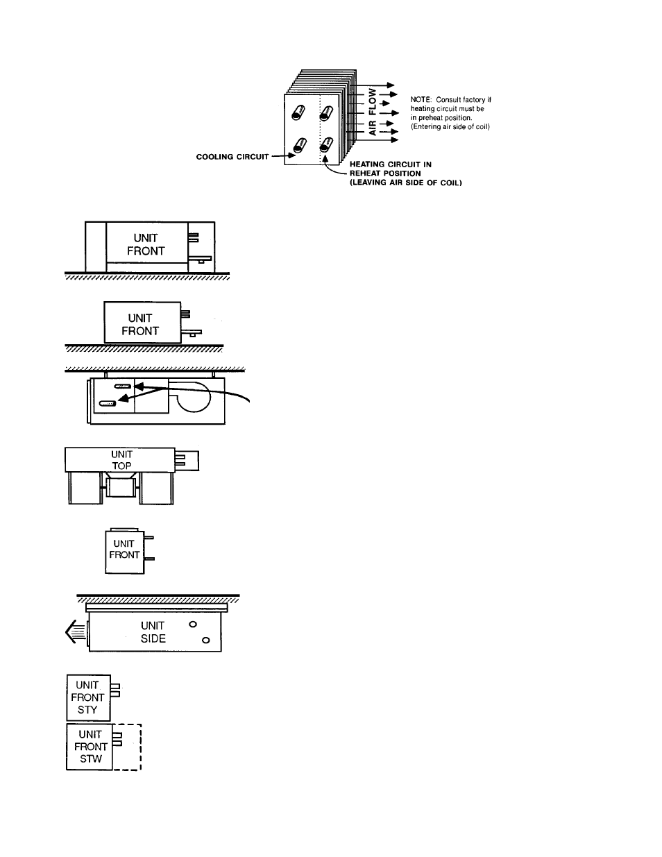
Hydronic Coil Arrangement
FIELD PIPING CONNECTIONS*
VERTICAL FLOOR UNITS — 42VB, VE, VF
Pipe into cabinet end compartment
(opening in bottom and back).
VERTICAL FLOOR UNITS — 42VA, VC
Pipe to external connections (no cabinet).
CEILING UNITS (EXPOSED) — 42CG, CK,
DE, DF
Pipe through knock-outs in rear of cabinet to
coil and valve package connections.
CEILING UNITS (CONCEALED) — 42CA,
CE, CF, DA, DC
Pipe to connections extending from end of
unit.
VERTICAL UNITS — 42DD
Pipe to stub connections extending from side
of unit.
HORIZONTAL AIR HANDLERS (BELT
DRIVE) — 42BH
Pipe to stub connections extending through
side of unit.
Valve packages are not factory supplied with
these units.
WALL UNITS, FURRED-IN
Pipe to stub connections at the side of unit.
or into optional piping compartment. Op-
tional piping compartment is required if valves
are factory installed. Factory installed valve
package is limited to one 2-way or 3-way mo-
torized valve and 2 hand valves.
*Location of field piping connections will vary depending on number of coil rows on factory-
supplied coil or arrangement of factory-supplied valves.
15