Control i/o connector functions – Toa SV-200MA User Manual
Page 36
36
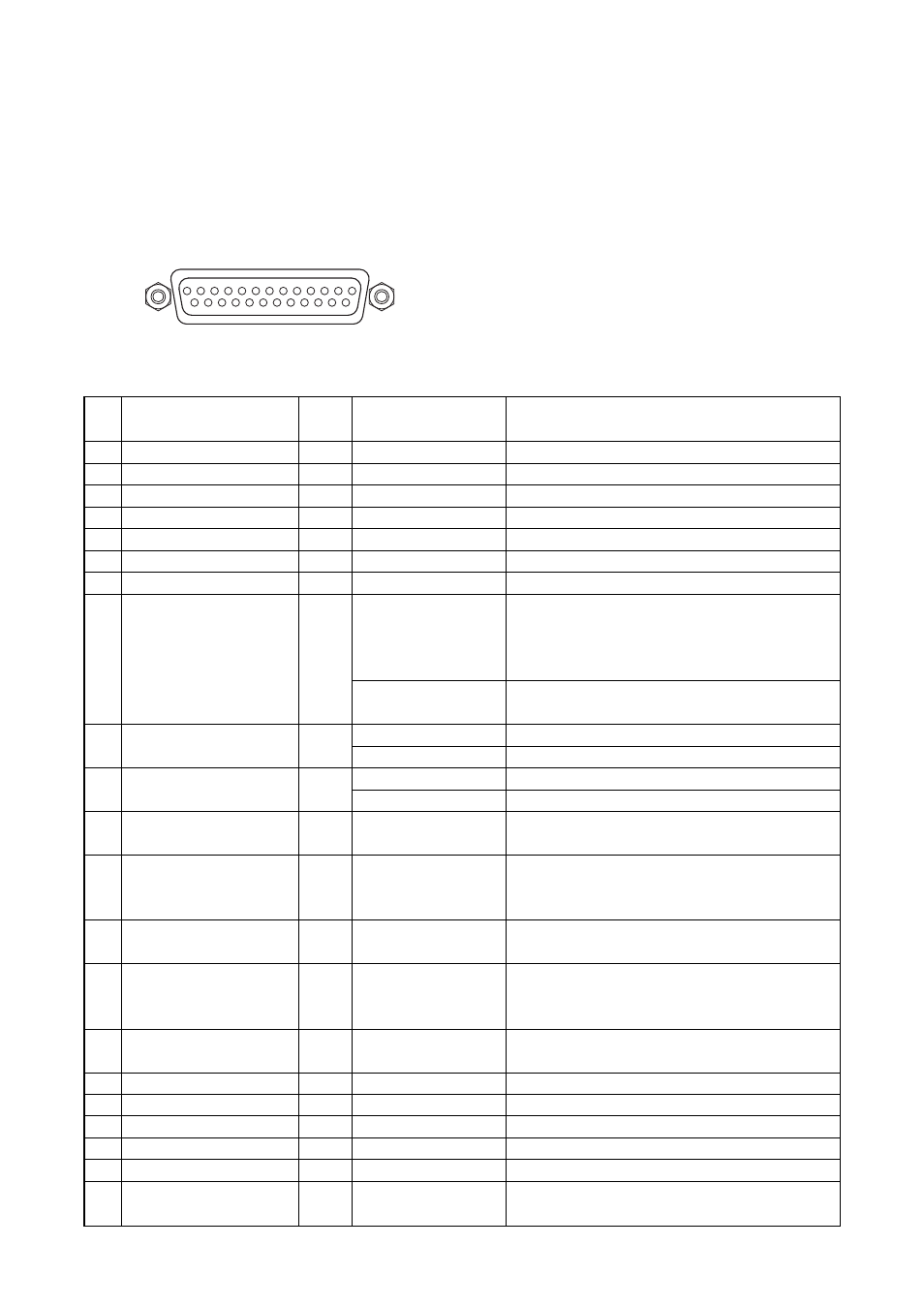
21. CONTROL I/O CONNECTOR FUNCTIONS
The rear panel-mounted Control I/O connector enables the VM amplifier to be controlled or monitored by
connected external equipment. Referring to the pin arrangement and functions, prepare the matching D-sub
male connector (screw-lock type) for connection to the external equipment. (See p. 10 No. 30 CONTROL I/O
connector.)
CONTROL I/O connector pin function table
VM amplifier's D-sub female connector
13
1
25
14
CONTROL I/O
Locking nut: 4-40 UNC
Function/status
When AC power is on
When DC power is on
Activates EV-200M Board's Message 1.*
1
Activates EV-200M Board's Message 2.*
1
Activates EV-200M Board's Message 3.*
1
Activates EV-200M Board's Message 4.*
1
Activates EV-200M Board's Message 5.*
1
Cuts off the VM amplifier's power amplifier
output.*
1
*
2
(External signals applied to
EXTERNAL SP INPUT go through to the
speakers.)
The VM amplifier's power amplifier output is
resumed.
Activates a start chime tone.
Activates an end chime tone (4-tone Down).
Turns power on.
Turns power off.
Activates the internal Westminster chime unit.
Places the unit in "Emergency broadcast" mode,
during which time an "Alert" announcement and
an "Evacuation" announcement are broadcast. *
1
Resets the unit from "Emergency broadcast"
mode.
Places the unit in "Emergency broadcast" mode,
during which time an "Evacuation" announcement
is repeated. *
1
The FAULT indicator lights to indicate external
equipment failure.
When the power switch is on by means of
manual or external control
Pin
No.
1
2
3
4
5
6
7
8
9
10
11
12
13
14
15
16
17
18
19
20
21
Signal name
AC power ON
DC power ON
Message 1 activation
Message 2 activation
Message 3 activation
Message 4 activation
Message 5 activation
VM amplifier's
broadcast cutoff control
Chime activation
(6 built-in chimes)
Power ON/OFF control
Westminster chime
activation
Emergency alert
activation
Emergency stop
activation
Emergency evacuation
activation
Failure indicator control
GND
GND
GND
GND
GND
Power switch on
IN
/OUT
OUT
OUT
IN
IN
IN
IN
IN
IN
IN
IN
IN
IN
IN
IN
IN
OUT
Signal/logic
Active Low
Active Low
One-shot make
One-shot make
One-shot make
One-shot make
One-shot make
At make
At break
Break-to-Make edge
Make-to-Break edge
Break-to-Make edge
Make-to-Break edge
One-shot make
One-shot make
One-shot make
One-shot make
At make
Active Low