Figure 4 controller operation flowchart 20, Figure 4, Controller operation flowchart – ThermoWorks 9103 HART SCIENTIFIC FIELD DRY-WELL TEMPERATURE CALIBRATORS User Manual
Page 24: Menu legend, Display temperature, Figure 4 controller operation flowchart
9103 Dry-Well
User’s Guide
20
UP
UP
DOWN
DOWN
SET
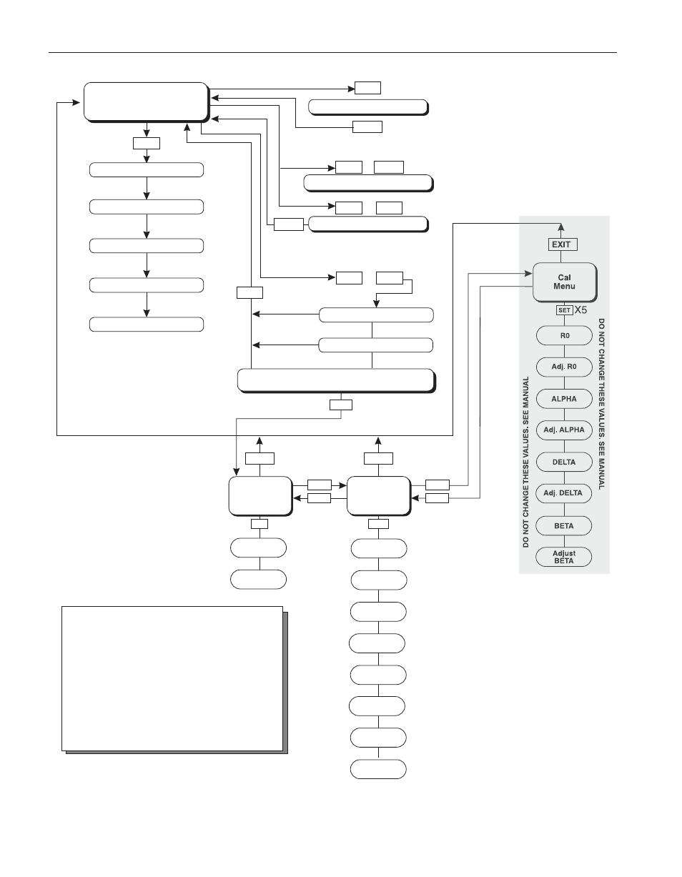
Operating
Parameters
Menu
SET
SET
Cal
Menu
ALPHA
DELTA
Adj. R0
DO NO
T CHANGE
THESE
V
ALUES.
SEE MANU
AL
DO NO
T CHANGE
THESE
V
ALUES.
SEE MANU
AL
Adj. ALPHA
Serial
Interface
Menu
BAUD
Rate
Adjust
BAUD Rate
Sample
Period
Adj. Sample
Period
Duplex
Mode
Adj. Duplex
Mode
Linefeed
Adjust
Linefeed
BETA
Adjust
BETA
EXIT
EXIT
EXIT
EXIT
EXIT
UP
DOWN
DOWN
SET
SET
SET
UP
+
+
+
Display Power
Toggles °C / °F
SET
SET
Select Setpoint
Adjust Setpoint
Units °C/°F
Scan On/Off
Scan Rate
Display
Temperature
Configuration Menu
Secondary Functions
X5
HL
Adj.HL
Displays Set-Point Resistance
Hold Temperature Display
EXIT
Set Proportional Band
R0
Adj. DELTA
Press “SET” to step through the menu and
to store the parameter value.
Press “EXIT” briefly to skip a parameter
without storing the parameter value.
Hold “EXIT” to exit the menu and display
the temperature
Menu Legend:
Figure 4 Controller Operation Flowchart
- LIMITED EDITION THERMAPEN (4 pages)
- LIMITED EDITION THERMAPEN Calibration Procedure (2 pages)
- SPLASH-PROOF SUPER-FAST THERMAPEN (4 pages)
- THERMADATA (RF) WIRELESS TEMPERATURE & DATA LOGGERS Studio (1 page)
- THERMADATA TEMPERATURE & HUMIDITY LOGGERS – SERIES II (1 page)
- TRIX-8 LOGTAG TRANSIT RECORDERS Quick Start Guide (2 pages)
- HACCP MOBILE FOR USE WITH BLUETHERM BLUETOOTH TEMPERATURE PROBE (1 page)
- 222-213 SPLASH-PROOF REFERENCE THERMAPEN (2 pages)
- 231-214 AIR THERMAPEN (2 pages)
- 231-279 PRO-SURFACE THERMAPEN (2 pages)
- RTR-61 WIRELESS HACCP RECORDING THERMOMETER (2 pages)
- 9882 PRINTING DATALOGGER THERMOMETER (54 pages)
- P750 PRINTING DATALOGGER THERMOMETER (28 pages)
- P795 PRINTING DATALOGGER THERMOMETER (9 pages)
- 222-550 PRECISION PLUS THERMOMETER (1 page)
- 232-042 THERMACHECK PLUS PRECISION THERMOMETER (4 pages)
- 226-042 THERMACHECK (2 pages)
- 292-701 SAF-T-LOG PAPERLESS HACCP THERMOMETER Quick Start Guide (4 pages)
- 292-701 SAF-T-LOG PAPERLESS HACCP THERMOMETER Operating Instructions (18 pages)
- 221-059 CATERTEMP PLUS (2 pages)
- 231-022 THERMA DIFFERENTIAL THERMOCOUPLE METER (2 pages)
- 232-101 THERMA WATERPROOF THERMOMETER (4 pages)
- 222-910 TEMPTEST 2 (2 pages)
- 221-051 THERMA K-PLUS (2 pages)
- 221-048 FOOD CHECK THERMOCOUPLE SYSTEM (2 pages)
- 261-550 THERMAMITE THERMOCOUPLE METER WITH FIXED PENETRATION PROBE (4 pages)
- TW8060 TWO-CHANNEL THERMOCOUPLE WITH ALARM (16 pages)
- CF-IR CLOSE FOCUS INFRARED THERMOMETER (2 pages)
- R-PRO PROFESSIONAL INFRARED THERMOMETER (2 pages)
- R-IND INDUSTRIAL INFRARED THERMOMETER WITH CIRCLE LASER Operating Instructions (2 pages)
- R-IND INDUSTRIAL INFRARED THERMOMETER WITH CIRCLE LASER Targeting Guide (1 page)
- IRK-2 INFRARED THERMOMETER Operating Instructions (4 pages)
- IRT INFRARED + TYPE T INPUT THERMOMETER (2 pages)
- 814-065 COMBO THERMOMETER INFRARED WITH FOLD OUT PROBE (3 pages)
- IRFS INFRARED FOOD SAFETY THERMOMETER (2 pages)
- IR-GUN-S INDUSTRIAL INFRARED THERMOMETER (2 pages)
- TW2 POCKET INFRARED THERMOMETER (1 page)
- IR-POCKET POCKET INFRARED THERMOMETER (1 page)
- 292-601 BLUETHERM DUO WITH BLUETHERM PRO FOR iOS Operating Instructions (2 pages)
- 292-601 BLUETHERM DUO WITH BLUETHERM PRO FOR iOS Quick Start Guide (1 page)
- 810-960 ECOTEMP ALARM THERMOMETER (1 page)
- PHARMALARM 2 MAX/MIN RECORDING THERMOMETER W/CAL CERTIFICATE (1 page)
- PHARMALARM 1 DIGITAL ALARM THERMOMETER W/ CAL CERTIFICATE (1 page)
- RT8100 FRIDGE/FREEZER ALARM THERMOMETER (1 page)
- RT8100MAT MIN/MAX RECORDING THERMOMETER WITH ALARMS (1 page)