Powering the rx375p, External device connections, Factory parameters – TeeJet RX375P Receiver User Manual
Page 8: Rx375p
6
www.teejet.com
RX375P
poweRIng the RX375p
Connect the RX375P to a TeeJet Technologies guidance system or
a 12 volt DC source with a power connector. Refer to Appendix D
for illustrations. Choosing the appropriate connector will depend on
specific installation requirements.
NOTE: It is recommended that a weather-tight connection and
connector be used if the connection will be located outside.
WARNING! Be careful not to provide a voltage higher than
the input range. This will damage the antenna.
The RX375P accepts an input voltage between 7 and 32 VDC via the
cable. For best performance, the supplied power should be continuous
and clean.
WARNING! Do not apply a voltage higher than 32 VDC.
This will damage the receiver and void the warranty.
The RX375P features reverse polarity protection to prevent excessive
damage if the power leads are accidentally reversed. With the
application of power, the RX375P will automatically proceed through an
internal start-up sequence. However, it will be ready to communicate
immediately.
NOTE: The initial start-up can take from 5 to 15 minutes depending
upon location.
NOTE: The RX375P can take up to five (5) minutes for a full
ionospheric map to be received from SBAS. Optimum accuracy
will be obtained once the RX375P is processing corrected
positions using complete ionospheric information.
eXteRnal DeVICe ConneCtIons
The serial ports of the RX375P operate at the RS-232C interface level
to communicate with external data loggers, navigation systems, and
other devices. The serial ports are accessible via the extension cable
that features a DB9 female data connector. The serial ports are also
used for firmware updates.
NOTE: For successful communication, the baud rate of the RX375P
serial port must be set to match that of the devices to which
they are connected.
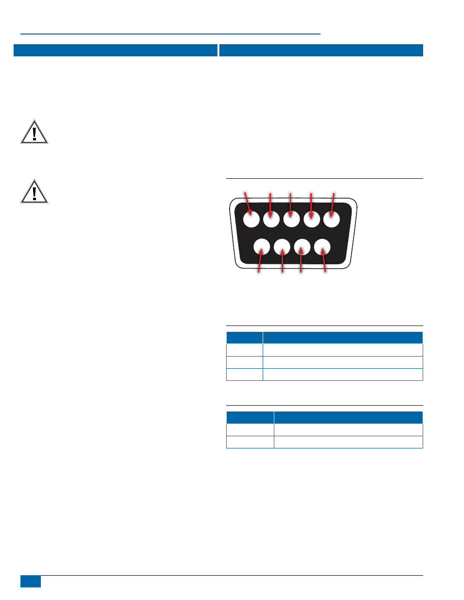
The following figure illustrates the numbering for the extension cable’s
DB9 socket connector (female). The associated numbering for the plug
connector (male) is a mirror reflection of the scheme illustrated.
Figure 3: DB9 Socket Numbering
1
2
3
5
6
4
7
8
9
NOTE: Other pins on the serial ports may be active depending on the
optional cable selection.
Table 3: Extension Cable Pin-Out, DB9
Pin Number
Function
2
Transmit RX375P NMEA 0183, binary and RTCM
3
Receive RX375P NMEA 0183, binary and RTCM input
5
Signal Ground
Factory Parameters
Table 4: DGPS Options
Application
Application 1
SBAS (WAAS, EGNOS, etc.)
Application 2
e-Dif (unsubscribed)