Rx375p placement, Routing and securing the cables, Mounting options – TeeJet RX375P Receiver User Manual
Page 7: Magnetic mount, Surface mount, Pole mount, Rx375p, Mounting rx375p placement
5
98-05327-ENUS R0
RX375P
MoUntIng
RX375p placement
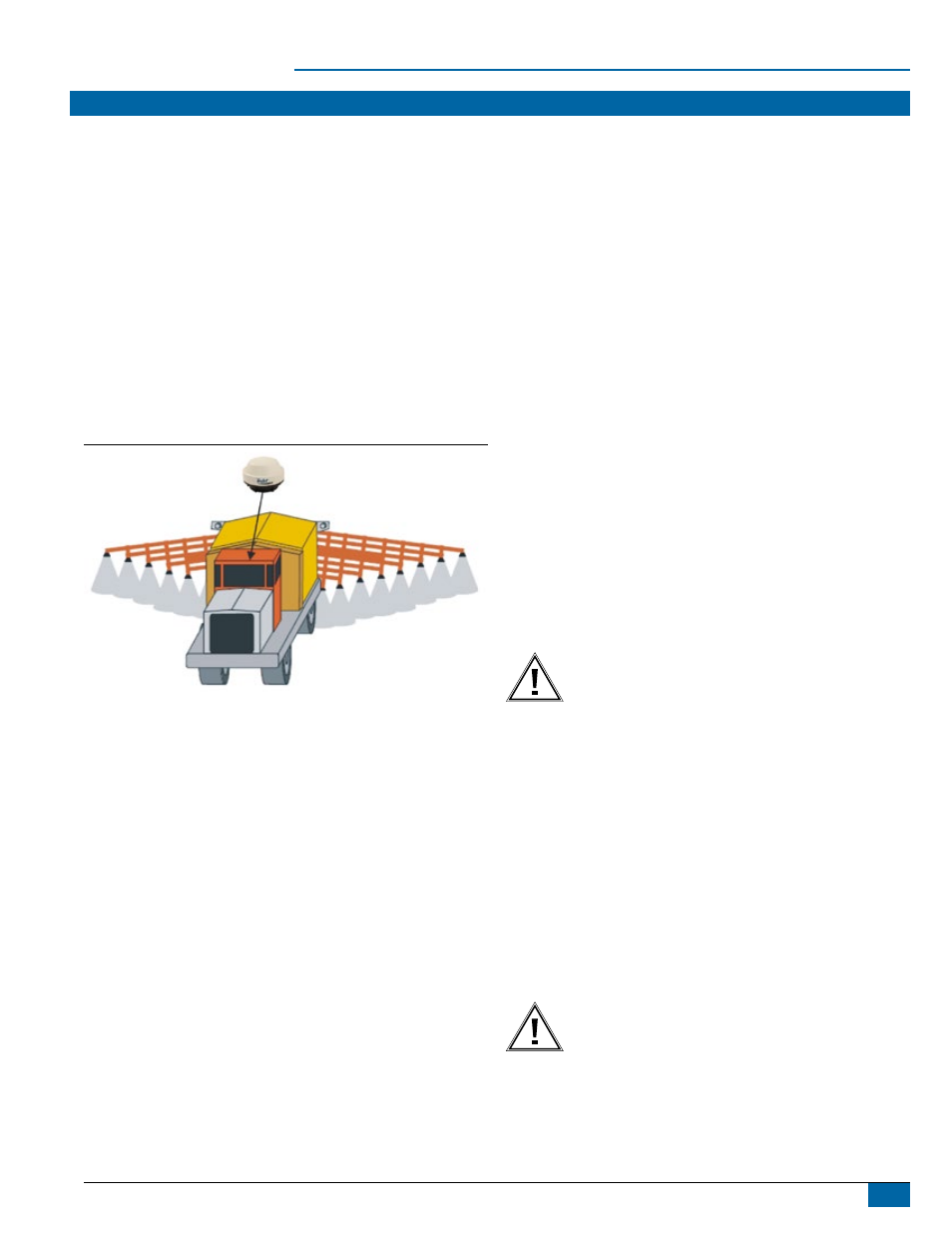
Placement of the RX375P is crucial to the system’s operation. The
GPS engine inside the RX375P computes a position based upon
measurements from each satellite to the internal GPS antenna unit.
Mount the RX375P to the identified point of interest. When choosing
a location, make certain there is an unobstructed view of the sky
available to the smart antenna. This will ensure that the GPS satellites
are not masked by obstructions, which can potentially reduce system
performance.
To place the RX375P:
1. Mount the RX375P on, or as close to the center of the point of
measurement.
2. Position the RX375P as high as possible.
The following illustration provides an example of the ideal location for
vehicle placement.
Figure 2: RX375P Vehicle Placement
Routing and Securing the Cables
Consider the following when routing cables:
• Power/data cable must reach an appropriate power source
• Power/data cable may connect to a data storage device,
computer, or other device that accepts GPS data
• Do not run cables in areas of excessive heat
• Do not expose cables to corrosive chemicals
• Do not crimp or excessively bend cables
• Do not place tension on cables
• Coil up excess cable in the cab of the vehicle or near the antenna
• Secure along the cable route using plastic tie wraps as necessary
• Do not run cables near high voltage or strong RF noise and
transmitter sources
WARNING! Improperly installed cables near machinery may cause
injury or death.
Mounting options
The RX375P can be mounted in several ways: Magnetic Mount,
Surface Mount or Pole Mount.
Magnetic Mount
The magnetic mount can be screwed into the bottom of the RX375P
and mounts to metal surfaces. A metal disc and foam adhesive are
included with each magnetic mount. Use the foam adhesive to bond
the metal disc to the desired mounting location if there are no metal
surfaces.
To use the metal disc and foam adhesive:
1. Clean and dry the mounting surface on the vehicle.
2. Remove the backing from one side of the foam adhesive and press
the metal plate onto the mounting surface on the vehicle.
3. Remove the backing from the other side of the foam adhesive.
4. Press the metal plate onto the mounting surface of the vehicle.
5. Apply firm pressure to ensure good adhesion.
6. Place the RX375P on top of the metal disc.
Surface Mount
As an alternative to the magnetic mount, the antenna is easily attached
to the surface with four machine screws (no. 8-32, not included).
To surface mount the antenna:
1. Use the templates located in Appendix C of this document, or
photocopy the bottom of the antenna and use it as a template to
plan the mounting hole locations
WARNING! Make sure the printout of the template or the
photocopy is scaled ONE TO ONE with the mounting holes
on the bottom of the antenna!
2. Mark the mounting hole centers as necessary on the
mounting surface.
NOTE: If using a photocopy of the receiver bottom, punch the
holes in the copy and use the back of the copy when marking
from the outside of the cab.
3. Place the antenna over the marks to ensure that the planned hole
centers agree with the true hole centers. Adjust as necessary.
4. Use a center punch on the hole centers in order to guide
the drill bit.
5. Drill the mounting holes with a 9 mm bit appropriate for
the surface mount.
6. Place the antenna over the mounting holes and insert
the mounting screws through the bottom of the mounting
surface and into the antenna.
WARNING! Install the antenna only hand-tight.
Damage resulting from overtightening the antenna is
not covered by warranty.
Pole Mount
The center thread of the antenna is 5/8 in (15.875 mm) for compatibility
with a survey pole (not included).