Guidance features details, Enter azimuth (deg), Mark a – TeeJet Matrix Pro 840G Start Up Guide User Manual
Page 7: A+ nudge feature, Azimuth degree, Field boundary
12
www.teejet.com
13
98-01380 R0
A
a+ Nudge feature
To adjust a AB guideline to your current location:
1. Press NAVIGATION & GUIDANCE OPTIONS icon to
display navigation options.
2. Press A+ NUDGE icon
A
to adjust the guideline to the
current location.
A
azimuth degree
To establish the azimuth guideline:
1. Press NAVIGATION & GUIDANCE OPTIONS icon to
display navigation options.
2. Press AZIMUTH icon
A
to enter azimuth degree.
3. Use the entry screen to establish the Azimuth degree.
4. Press:
►Accept to save the settings
►Cancel to leave the keypad without saving
5. “Would you like to name this guideline?”
Press
►Yes – to enter a name and save the guideline.
►No – to automatically generate a name.
The console will begin providing navigation information.
To establish additional azimuth guidelines, follow the same
steps as the initial azimuth guideline.
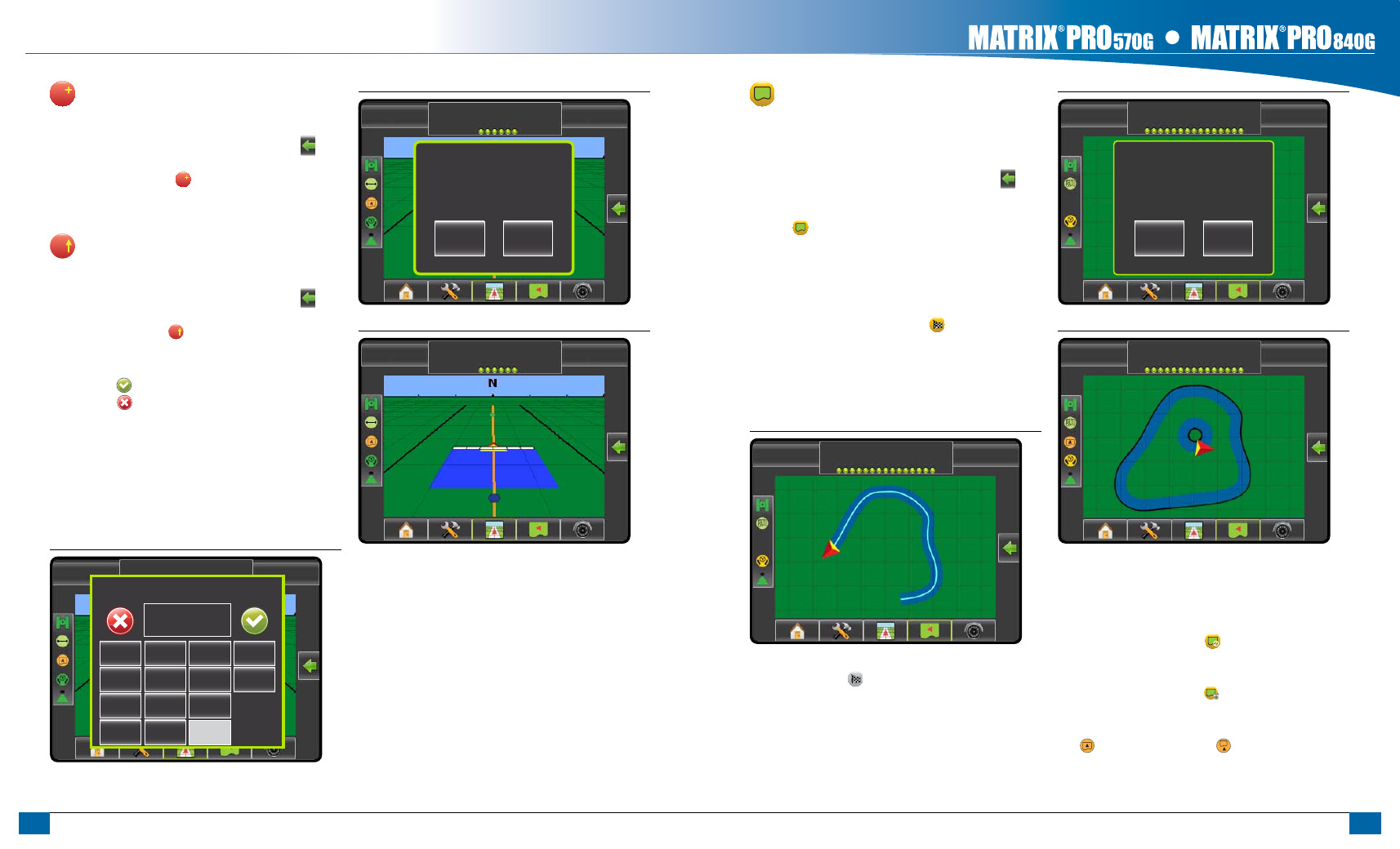
Figure 1-6: Azimuth Degree
-13
7.2
mph
> 0.0 <
Enter Azimuth (Deg)
1
2
3
Clear
4
5
6
<--
7
8
9
0
.
+/-
Figure 1-7: Save Guideline
-13
7.2 mph
> 0.0 <
Would you like to name this guideline?
Yes
No
Figure 1-8: Follow Guidance
0 deg
7.2 mph
> 0.0 <
field Boundary
To establish a field boundary:
1. Drive to a desired location at the perimeter of the field/
area.
2. Press NAVIGATION & GUIDANCE OPTIONS icon to
display navigation options.
3. While the vehicle is in motion, press BOUNDARY
icon .
4. Travel the perimeter of the field/area.
5. Finish boundary:
►Travel to within one swath width of the starting point. The
boundary will close automatically (the white guideline will
turn black).
►Press BOUNDARY FINISH icon . A straight line will
complete the boundary between your current location and
the starting point.
6. Press:
►Yes – to save the boundary.
►No – to delete the boundary.
Figure 1-9: Boundary in Progress
-13
7.2 mph
Mark A
NOTE: On the external or initial boundary, the BOUNDARY
FINISH icon is not available for selection (grayed
out) until the minimum distance is travelled (five-times
the swath width).
To create an interior boundary, follow the same steps as the
initial boundary.
Figure 1-10: Save Boundary - Field View
-13
7.2 mph
Mark A
Area bounded = 14.45 ac
Press “Yes” to save the marked
boundary or “No” to delete the
boundary.
Yes
No
Figure 1-11: Boundaries Complete
-13
7.2 mph
Mark A
If a swath was applied while creating an external or initial
boundary, the boundary line will be to the exterior of the applied
swath. If a swath was applied while creating an interior or
additional boundary, the boundary line will be to the interior of
the applied swath.
Use CANCEL BOUNDARY icon to cancel the new field
boundary process and revert to the previous boundary (when
established).
Use DELETE BOUNDARY icon to delete all field boundaries
for the current job.
In correspondence to your current location, the IN BOUNDARY
icon or OUT BOUNDARY icon is displayed on the
Status Bar once the boundary is established.
GuidaNce featureS detaiLS