744a sprayer control, Figure 1-2: ball valves – TeeJet 744A Sprayer Control User Manual
Page 5
www.teejet.com
2
744A Sprayer Control
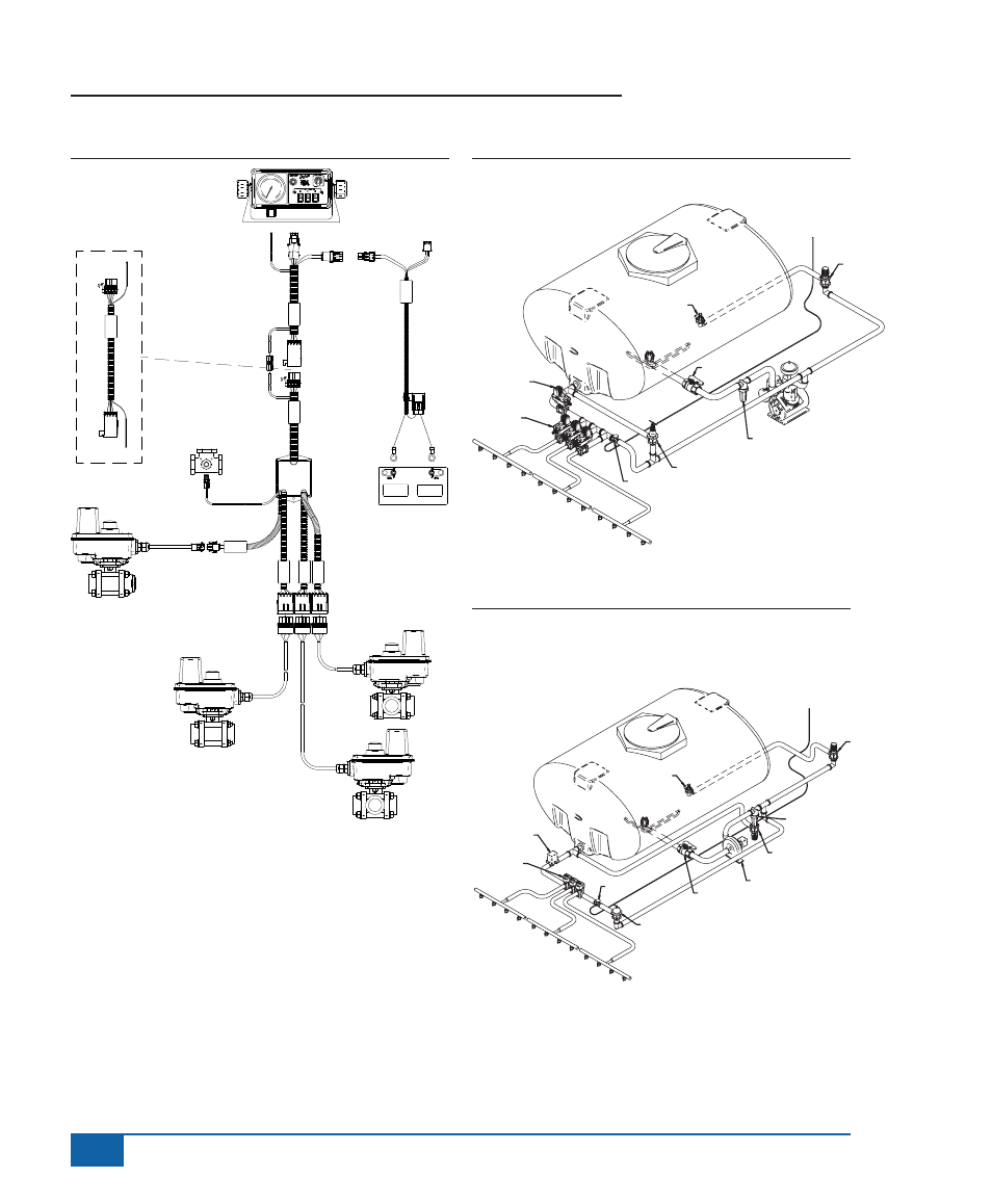
Figure 1-2: Ball Valves
45
-0
53
85
D
C
: x
x/x
x
Te
eJ
et
DC:
X
X
/X
X
45
-1
00
72
Te
eJ
et
45
-1
00
80
D
C
:
xx
/x
x
B
oo
m
3
B
oo
m
2
B
oo
m
1
Reg. Valve
T
ee
Je
t
45
-1
00
86
D
C
:
xx
/x
x
744A Console
Cable, Power
Fused
45-05385
Battery
Harness, 744
Console 12’
45-10072
Cable, Extension
10’ 45-10086
Harness, 744 Ball
Valve 45-10080
Valve, Regulating
35-02115
Ball Valves
Figure 1-3: Plumbing Diagram - Diaphragm Pump
Figure 1-4: Plumbing Diagram - Centrifugal Pump
and Self-Cleaning Strainer
Boom 1
Boom 2
Boom 3
Boom Valves 1-3
Regulating Valve
Gauge Tee
Pressure Relief
Valve
Tank Shut Off
Line Strainer
Diaphragm Pump
Throttling Valve
To 744A
Controller
Jet Agitatior
To 744A
Controller
Throttling Valve
Throttling
Valve
Gauge Tee
Tank
Shut-Off
Centrifugal
Pump
Throttling Valve
Line Strainer
Elecrical
Regulating
Valve
Directo Valve
Boom 1
Boom 2
Boom3
Jet Agitator
- Sentry 6140 (16 pages)
- 801 flowmeter (2 pages)
- GPS Speed Sensor (2 pages)
- IC18 SPREADER JOB COMPUTER (47 pages)
- IC18 SPREADER JOB COMPUTER (32 pages)
- IC18 SPRAYER JOB COMPUTER (43 pages)
- IC18 SPRAYER JOB COMPUTER (68 pages)
- IC18 NH3 JOB COMPUTER (63 pages)
- BOOMPILOT JOB COMPUTER (21 pages)
- BOOMPILOT JOB COMPUTER (32 pages)
- MATRIX 570VT Software version 1.00 (12 pages)
- MATRIX 570VT Software version 1.00 (20 pages)
- MT 600 Piston Injection Pump (6 pages)
- BoomPilot (2 pages)
- BoomPilot Pro Metric (2 pages)
- BoomPilot Pro (2 pages)
- 500 SLURRY COMPUTER (30 pages)
- 70 Series Speed Area Monitor (2 pages)
- 70 Series EPC - Manual Pump (4 pages)
- 70 Series Fill Flow (2 pages)
- 70 Series Flow Volume Monitor (2 pages)
- ARC-6000 (50 pages)
- TASC-6000 (78 pages)
- TASC-6100 (86 pages)
- TASC-6200 (50 pages)
- TASC-6200 (45 pages)
- TASC DATA LOGGER (17 pages)
- TASC PRINTER MODULE (8 pages)
- TASC-6000 Supplement (9 pages)
- 744E AUTO BOOM SECTION CONTROL (8 pages)
- 744E SPRAYER CONTROL (16 pages)
- 814-AB Airblast Sprayer Monitor (15 pages)
- 834 Sprayer Control (15 pages)
- 834 Sprayer Control L2.12 (15 pages)
- 834-P Sprayer Control (18 pages)
- 844 Sprayer Control (44 pages)
- 844 Operations Mini (2 pages)
- 844-AB Sprayer Control (24 pages)
- 844-E Sprayer Control (36 pages)
- 844-R Speed Compensated Application Control (32 pages)
- 854 Sprayer Control (52 pages)
- 026 – 73 AddFlow (8 pages)
- LH 3000 (24 pages)
- LH 4000 (44 pages)