744a sprayer control, Input power cable, Pressure gauge – TeeJet 744A Sprayer Control User Manual
Page 11
www.teejet.com
8
744A Sprayer Control
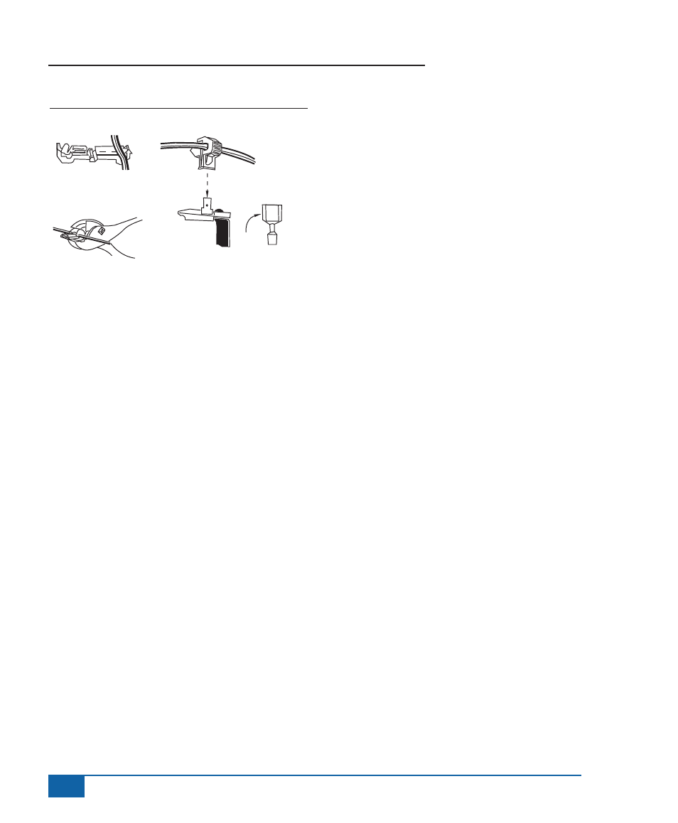
Figure 2-2: Figure 2-2: T-Tap Connector Assembly
Step A
Step B
Step C
To Terminal of
144 Directo Valve
Ball
Valve
Connector
Input Power Cable
The Input Power Cable consists of three wires. The
red wire should be connected to a 12 Volt power
supply within the cab of the vehicle (i.e., ignition
switch). If the power source is located outside of the
cab, the power cable should exit the cab through
the same 1.0” (3.0 cm) diameter hole as the output
control cable. The blue wire should be connected
to the headlight system of the tractor. This can
be accomplished by connecting the blue wire to
the auxiliary terminal of the headlight switch or by
splicing into the wire connected to the headlight.
The black wire is the negative lead and should be
connected to a good chassis ground.
Plug the input power cable into the power cable
socket on the back of the 744A console. Turn the
vehicle ignition switch to the “Run” position. If the
wiring has been connected properly, the boom
section indicator lights should illuminate when the
boom section switches are toggled. The gauge light
should appear when the headlights are illuminated.
Pressure Gauge
The tubing for the pressure gauge is supplied
as part of the wiring harness. To avoid chemical
leakage into the vehicle cab, the tube coupler
should be installed outside of the vehicle cab. If a
gauge isolator is used with the system, it should be
installed in place of the coupler, also outside of the
vehicle cab.
The pressure gauge should be checked for
accuracy each season. If the unit is equipped with
a liquid-filled gauge and it does not read accurately,
the gauge may need to be vented. To vent the
gauge, remove the four screws in the back of the
sprayer control housing and lift off the back. The
rear of the gauge will be exposed. To vent the
gauge, clip off the nib of the rubber plug in the back
of the gauge or puncture it with a needle. Once the
gauge has been vented, do not store the sprayer
control on its back as this may cause a loss of
fluid from within the gauge. If further inaccuracy
is suspected at 0 PSI and a gauge isolator is
being used, the isolator line may need to be bled
according to the instructions furnished with the
gauge isolator.