744a sprayer control, Chapter 2 - installation mounting bracket, Output control cable – TeeJet 744A Sprayer Control User Manual
Page 10: 744a-3 unit
www.teejet.com
7
744A Sprayer Control
CHAPTER 2 - INSTALLATION
MOUNTING BRACKET
1. Make sure all switches on the 744A Sprayer
Control are turned to the “Off” position.
2. Determine the best location for the 744A Sprayer
Control in the vehicle cab according to the
following guidelines:
• pressure gauge should be readily visible
• switches should be within easy reach
• controller bracket should rest on a flat surface
• 12 volt DC power source must be accessible
(maximum draw 10 amps)
3. Determine the proper routing for power cables
and pressure tube:
• away from operators’ movement area
• away from moving parts
• away from sharp objects
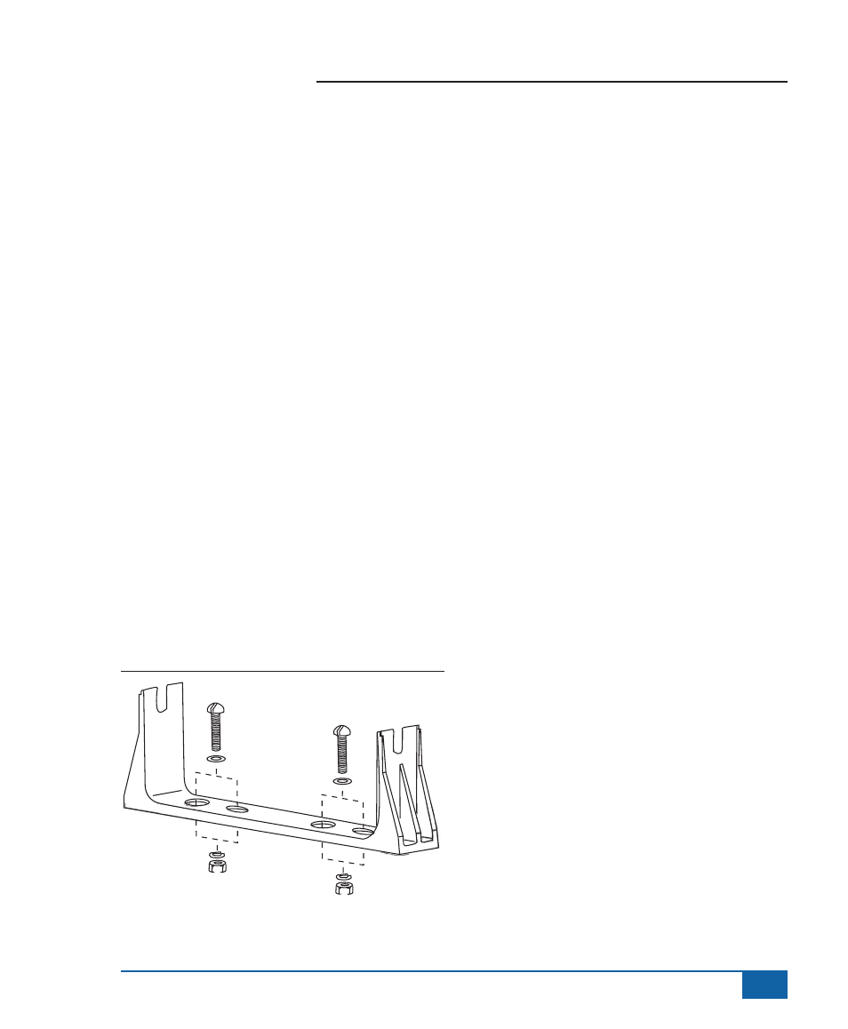
4. Install the mounting bracket using ¼” (6.4mm)
drill, machine screws, nut, washers, and lock
washers as illustrated below. Attach the control
housing assembly to the mounting bracket using
the console adjusting knobs and washers.
Figure 2-1: Mounting Bracket
OUTPUT CONTROL CABLE
Cut a 1.0” (3.0 cm) diameter opening used to feed
the output control cable from the interior of the
tractor cab to the boom control valves. Make sure
the hole has no burrs or sharp edges that could
damage the wires.
744A-3 Unit
6 wires from the output cable are used to control a
three-section boom.
• Orange (Right) Yellow (Center) Green (Left) –
connect to 144A Valves. When using a
*344AEC Ball Valve, connect to the white wire.
• **Black – connect to other terminal on 144A
Valves. When using the *344AEC Ball Valve,
black is not connected.
• Red and Brown – connect to red and black
wires on the Regulator Valve (244, 344AE-PR,
or 344AE-RL).
*When using 344AEC DirectoValve® Ball Valves, connect black
wire(s) and red wire(s) using the Valve End and Battery End
Cables (supplied only when Ball Valve Kits are purchased) to an
uninterrupted power supply such as the battery.
**The black ground wire for the control cable is not supplied
with connectors attached. The T-Tap connectors are supplied
separately and should be attached as per Figure 2-2.
WARNING!: Do not plug the control cable into the
control box until it has been fully connected
to the control valves. Doing so may allow the
unconnected leads to short out.