Crestron electronic QM-FTCC User Manual
Page 28
QuickMedia™ FlipTop Computer Center
Crestron QM-FTCC
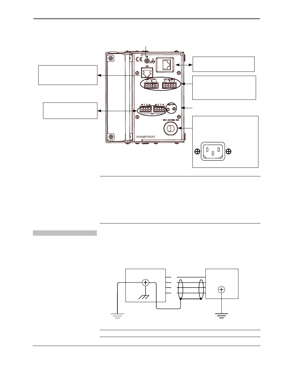
Hardware Connections for the QM-FTCC (Bottom)
MIC/LINE LEVEL INPUTS:
FROM BALANCED CONDENSER
OR DYNAMIC MICROPHONES OR
BALANCED/UNBALANCED LINE
LEVEL SOURCES
120 VAC LINE CORD
(DOMESTIC MODELS)
(INTERNATIONAL MODELS)
ETHERNET PASS THROUGH:
10/100BaseT ETHERNET TO LAN
GROUND
QM:
QUICKMEDIA PORT CARRIES
AUDIO, VIDEO, RGB AND MIC
OUTPUT OVER CAT5
NET:
TO CONTROL SYSTEM AND
OTHER CRESNET DEVICES
TSID SETUP BUTTON AND LED
IEC-320
ELECTRICAL
APPLIANCE
COUPLER
250V~50/60Hz 10A
NOTE: For optimum performance, Crestron strongly recommends using
CresCAT-QM cable, available from Crestron. Other high-quality/low skew
CAT5e/CAT6 wiring may also be used with varying performance.
NOTE: The maximum continuous current from equipment under any external load
conditions shall not exceed a current limit that is suitable for the minimum wire
gauge used in interconnecting cables. The ratings on the connecting unit's supply
input should be considered to prevent overloading the wiring.
Ground Wire Connections
Proper grounding is required. Connect the ground from the QM transmitter
(QM-FTCC) to earth ground. Connect the Cresnet shield at the QM-RMCRX-BA to
the chassis ground provided on the QM-RMCRX-BA. The QM-RMCRX-BA chassis
must also be connected to an earth ground (building steel). Refer to the following
grounding diagram.
Ground Wire Connections
QM-RMCRX-BA
24
Y
Z
G
Shield
Ground
Wire to
Earth
Ground
Ground
Terminal
to Earth
Ground
Cresnet
Ground Wire
QM-FTCC
NOTE: Do not connect the shield to earth ground at the QM-FTCC.
24
• QuickMedia™ FlipTop Computer Center: QM-FTCC
Operations & Installation Guide – DOC. 6313B