Crestron electronic QM-FTCC User Manual
Page 16
QuickMedia™ FlipTop Computer Center
Crestron QM-FTCC
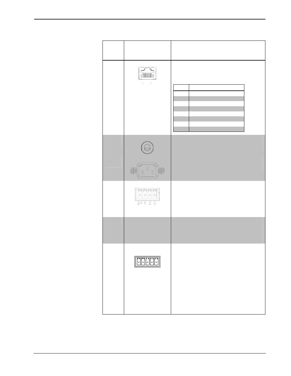
Connectors, Controls & Indicators (Continued)
#
CONNECTORS
1
,
CONTROLS &
INDICATORS
DESCRIPTION
8
LAN
8
1
(1) 8-pin RJ-45 female, Ethernet LAN pass
through jack for connection to Ethernet,
providing local area network or Web access
(cable not included)
PIN
SIGNALS
1
TD+
2
TD-
3
RD+
4
Connected to pin 5
5
Connected to pin 4
6
RD-
7
Connected to pin 8
8
Connected to pin 7
9
(QM)
125 V
(1) 9 foot grounded AC line cord
Passes through to front panel AC power
outlet
9
(QMI)
MAX 250 V
(1) IEC socket
Passes through to front panel AC power
outlet
10
NET
(2) Four-position terminal block connectors
for data and power. Connects to Cresnet
control network.
Pin 1 (24) Power (24 Volts DC)
Pin 2 (Y)
Data
Pin 3 (Z)
Data
Pin 4 (G)
Ground
11
SETUP LED &
BUTTON
(1) Red LED and miniature pushbutton, used
for touch-settable ID (TSID)
Used for setting network ID during initial
configuration or when the device is being
added/replaced.
12
MIC/LINE (1 – 2)
G
-
+
- +
(2) 5-pin 3.5 mm detachable terminal blocks
Balanced microphone/line inputs
Balanced mic input level: -60 to - 20 dBV
nominal
Balanced line input level: -28 to + 12 dBV;
4 V
rms
maximum
Unbalanced line input level: -34 to + 6 dBV;
2 V
rms
maximum
Mic input impedance: 10k ohms, accepts 60
to 600 ohm source
Line input impedance: 22k ohms balanced,
11k ohms unbalanced
Phantom power: 10 mA (total) @ 48 Volts
DC, software enabled to both MIC inputs
(Continued on following page)
12
• QuickMedia™ FlipTop Computer Center: QM-FTCC
Operations & Installation Guide – DOC. 6313B