Crestron electronic QM-FTCC User Manual
Page 15
Crestron QM-FTCC
QuickMedia™ FlipTop Computer Center
Connectors, Controls & Indicators
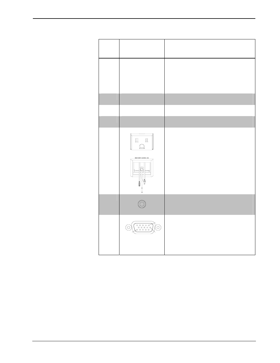
#
CONNECTORS
1
,
CONTROLS &
INDICATORS
DESCRIPTION
1 KEYPAD
2
Programmable keypad allowing variable
combinations of large and small engravable
buttons, 10 minimum (all large) to 20
maximum (all small); ships with 10 large
buttons (small buttons and engraving sold
separately)
(1) red LED per button, programmable
2
PWR LED
2
(1) Green LED, indicates 24 Volts DC power
supplied from Cresnet control network
3 NET
LED
2
(1) Yellow LED, indicates communication
with Cresnet system
4
BAR GRAPHS
2
(2) Red 8-segment LED bar graphs,
programmable
5
(QM)
125V
(1) Grounded AC socket, AC power pass
through outlet
Maximum load: 10 Amps @ 125 Volts AC,
50/60 Hz
5
(QMI)
MAX 250V
(1) Grounded AC socket, AC power pass
through outlet
Specify socket type: PWR-AU-B
(Australia/China), PWR-EU-B (Europe
“Schuko”), PWR-FR-B (France), PWR-IT-B
(Italy) or PWR-UK-B (UK)
Maximum load: 10 Amps @ 250 Volts AC,
50/60 Hz
6
AUDIO
(1) 3.5 mm TRS mini phone jack
Unbalanced stereo line level audio input
Minimum input level: 1 V
rms
Input impedance: 10k ohms
7
COMPUTER
3
Pin 1
Pin 6
Pin 15
(1) DB15HD female
RGB(VGA)/component video
4
input
Formats: RGBHV, RGBS, RG
s
B, YP
b
P
r
Input impedance: 75 ohms
H/V sync impedance: 1k ohms
Maximum input level: 1 V
p-p
Maximum H/V sync level 5 V
p-p
Signal detection on H, Y and G
s
(Continued on following page)
Operations & Installation Guide – DOC. 6313B
QuickMedia™ FlipTop Computer Center: QM-FTCC
• 11