Installation, 5 installation – SeaLand 9400 Series RushFlush Installation User Manual
Page 7
7
SeaLand 9300-9400 Series RushFlush Toilets
Installation
5 Installation
5.1
General guidelines
For optimum toilet system preformance, follow these guidelines . Make sure to also follow any
governing codes or standards that apply to your installation .
Fresh Water Supply System Plumbing (fig .
2
, page 2)
DO NOT USE RAW WATER SUPPLY
1 . All water supply system plumbing should be 1 in . ID, with working pressure ratings above the
maximum water pump pressure . (100 PSI minimum recommended) .
2 . Water inlet strainer: 1 in . ID, 40 mesh
3 . Pressure gauge: 0-100 PSI
4 . Water pump: Grundfos
®
MQ3-35 or equivalent is recommended .
• 1 in . NPT connections
• Internal pressure switch: 50 PSI cut-out, 30 PSI cut-in
• Pump current draw is 8 amps @ 110V, 4 amps @ 220V, other pump manufacturers may vary .
• 15 GPM needed; pump actually rated at 22 GPM max . flow with no restrictions
• Depending on pump installation parameters, a pump of adequate suction lift capability
should be considered . The MQ3 pump has 25 feet of suction lift capability, but it varies
depending on horizontal suction run .
5 . Potable water pressure (accumulator) tank: AMTROL
®
Well-X-Trol
®
WX-105-PS or equivalent
is recommended .
• 3/4 in . NPT, or larger, connection
• 5 gallon total volume, 1 .8 gallon drawdown @ 30/50 PSI
• Air pressure charge should be set to 2-4 PSI below pump cut-in pressure .
• One 5-gal . accumulator tank recommended for up to 6 heads .
6 . Pressure relief valve:
• Installation recommended by accumulator tank manufacturer
• Should be installed near accumulator tank and pump, and set to open at excessive water
system pressures . This protects fresh water system in case of pressure switch malfunction .
7 . Check valve: will isolate the toilet system from the rest of the onboard freshwater system;
spring check, 1 in .
8 . Rim wash valve inside toilet:
• 1/2 in . NPT connection
• This water supply line can intersect from main 1 in . distribution line prior to high-flow water
jet valve using 1/2 in . plumbing to toilet .
9 .
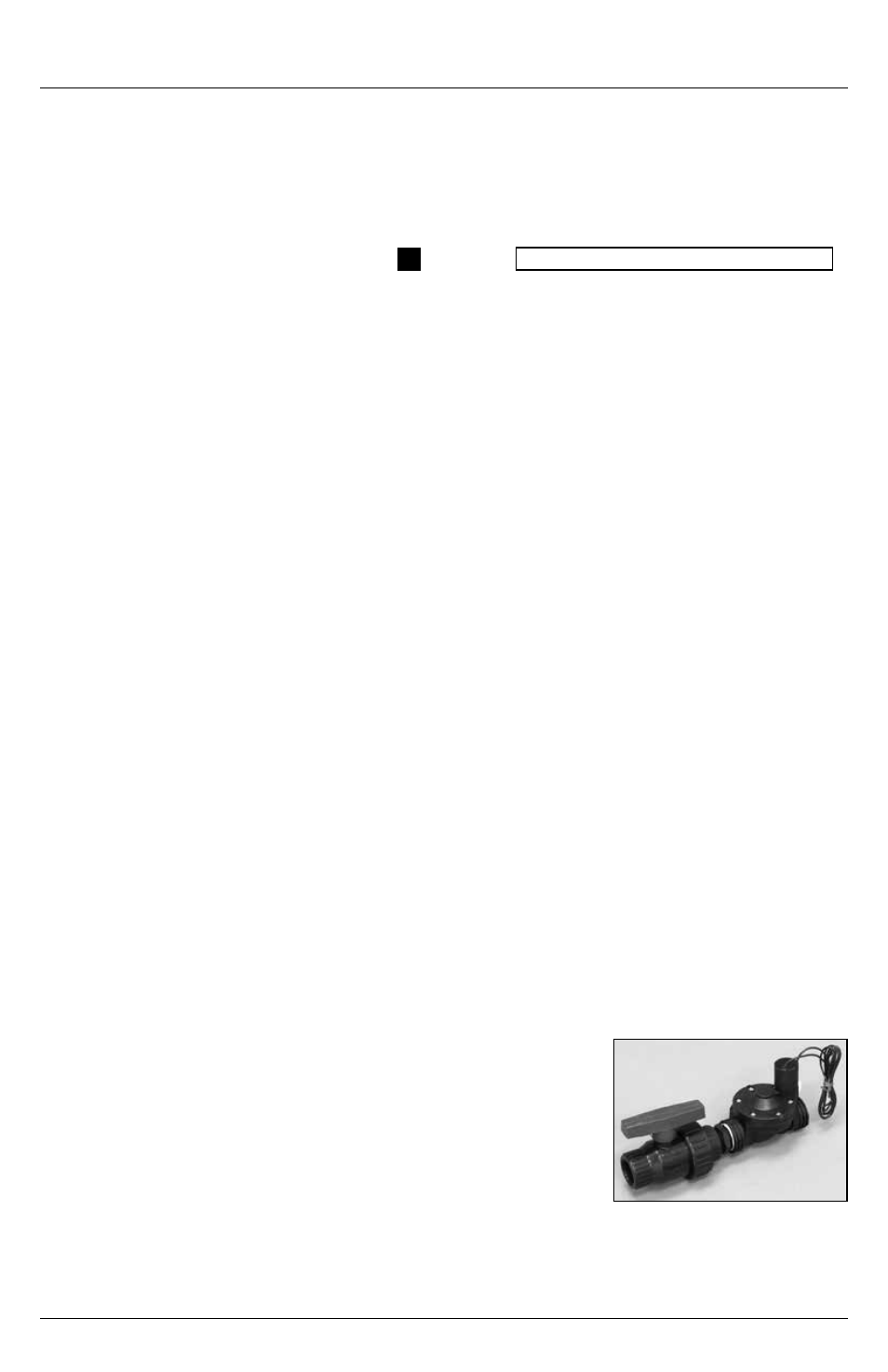
Electric high-flow water jet valve and maintenance ball valve, supplied with every toilet:
• 1 in . NPT connections
• Water jet valve should be closest to toilet . Maintenance ball
valve should be farthest from toilet – refer to direction arrow on
top of water jet valve inlet port .
• An in-line strainer is installed into the water jet valve inlet at the
factory . The cone shape protrudes out and against the direc-
tion of water flow away from the center of the valve, pointing
towards the maintenance ball valve .
• The water jet valve features a small white manual override lever
located next to the solenoid . This must be vertical for correct electrical operation . However,
it can be turned to the horizontal position to manually test the water system . Be sure to
return it back to vertical when testing is finished .
Electric water
jet valve