SeaLand 9400 Series RushFlush Installation User Manual
Page 11
11
SeaLand 9300-9400 Series RushFlush Toilets
Installation
19
5.3
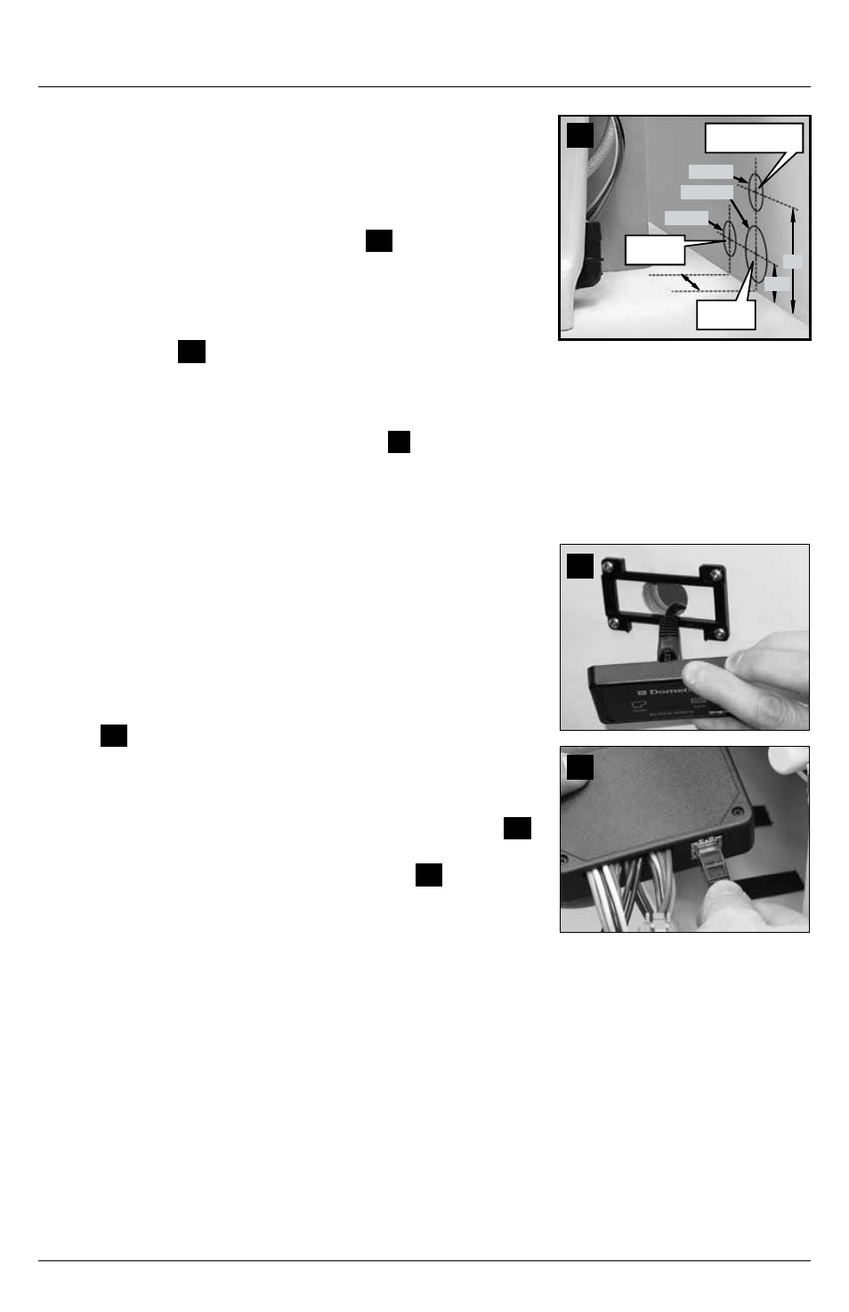
Toilet with through-the-wall connections
1 . To install wiring and plumbing connections through the wall,
determine the primary centerline location as described in
Section 5.2, steps 2 and 3 .
2 . Mark horizontal primary centerline for plumbing and wiring
access holes on wall according to fig .
19
. Mark secondary
centerline for lower bowl water line 3 in . (76 mm) to left of
primary centerline . Mark hole locations as indicated .
3 . Drill two 1-1/2 in . (38 mm) dia . holes for water supply lines
and wiring, and drill 2 .25 in . (57 mm) dia . hole for discharge
plumbing (fig .
19
) .
4 . Follow toilet installation instructions beginning at Section 5.2,
step 15 . For lower bowl water line, install an elbow fitting (not
provided) so that 1 in . ID flexible water line can loop upward
and back down to inlet at toilet base (fig .
3
7, p . 2) .
5 . Before securing toilet to floor with lag bolts (step 25), be sure
to drill 3/16 in . pilot holes .
5.4
9300 series toilet system status panel
(optional accessory)
1 . Plan status panel location so that electrical connections can
be made between toilet and status panel with wiring cable
provided . Be sure cable and connections cannot get wet .
2 . Use Dometic wall switch template to mark location of
fastener and access holes for status panel . Drill 1 in . (25 mm)
wiring access hole, then fasten panel bracket to wall
(fig .
20
) .
3 . Attach cable (provided with status panel) to status panel’s
RJ45 connector, then route other end of cable through wall
access hole to floor access hole at toilet base .
4 . Snap the status panel cover onto the panel bracket (fig .
20
) .
5 . WITH ELECTRICAL POWER OFF, connect cable from the
status panel to the toilet control module (fig .
21
) . To attach
RJ45 connector, remove control module from back of toilet
(locking fabric strips will come apart), route cable up through
toilet plumbing lines to connect to module, then re-attach
control module to back of toilet .
6 . After all toilet wiring connections are made, turn on
electrical power to toilet system . A steady green “Power On”
light indicates that electrical power to the toilet is activated .
20
21
3 in.
4 in.
1.5 in.
1.5 in. dia.
2.25 in. dia.
1.5 in. dia.
Lower bowl
water line
Upper rim water line,
electrical wires
Discharge
outlet