SeaLand 9400 Series RushFlush Installation User Manual
Page 10
10
Installation
SeaLand 9300-9400 Series RushFlush Toilets
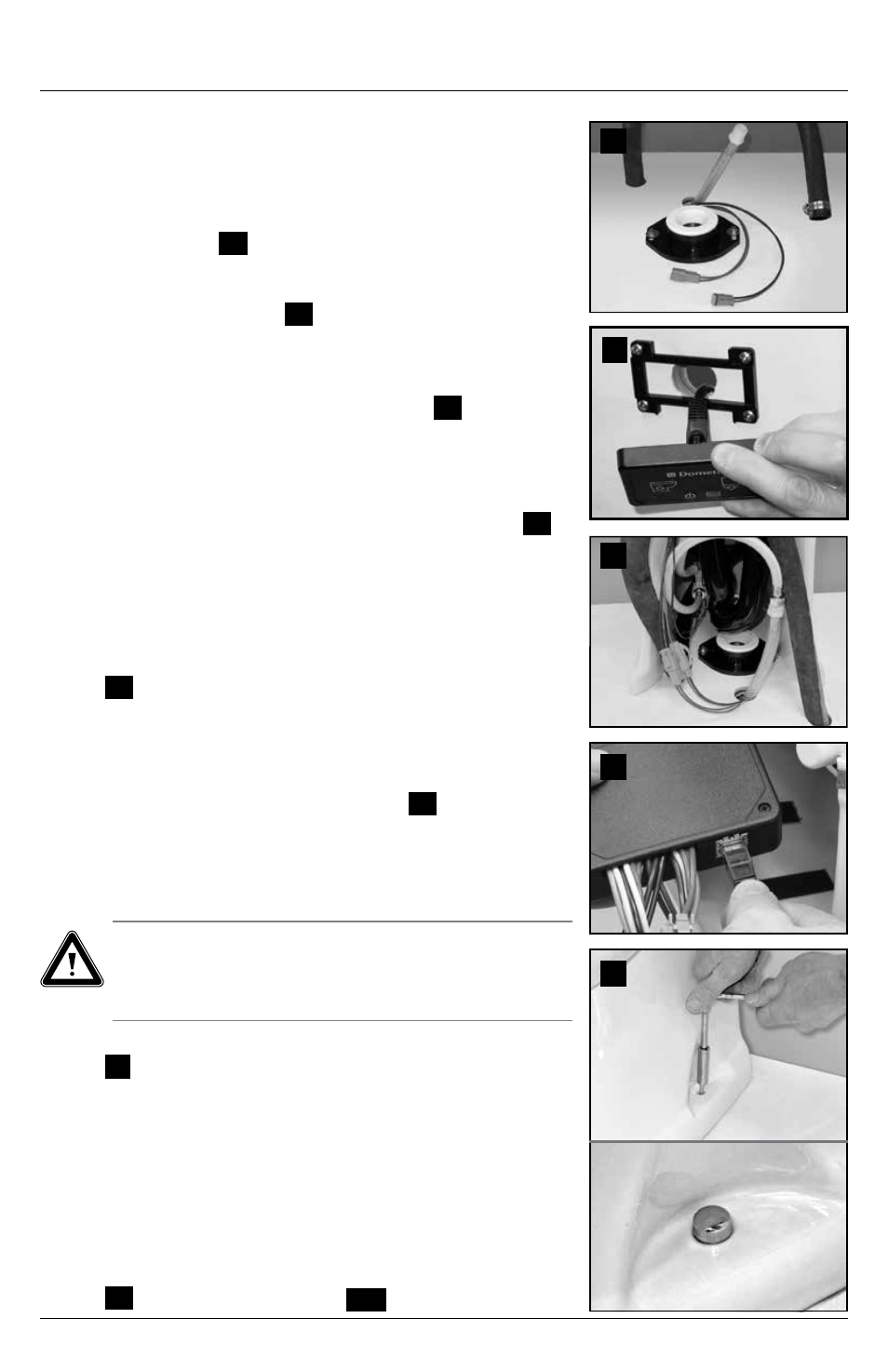
14 . Carefully raise toilet up from floor flange and set aside . Tight-
en floor flange screws (if loose for adjustment) . Drill 3/16 in .
pilot holes in the floor for the ceramic toilet mounting bolts .
15 . Route 1/2 in . ID upper rim water line through the hole on the
primary centerline . Provide 1/2 in . NPT connection for upper
rim water line (fig .
14
) .
16 . Route 1 in . ID lower bowl water line through the hole on the
secondary centerline, leaving about 3 feet of extra hose to
create a flexible loop (fig .
14
) .
17 . WITH ELECTRICAL POWER OFF, route #18 gauge stranded
copper wire from DC power source (positive and ground)
through a fuse or circuit breaker . Leave at least 18 in .
(457 mm) of wire for connecting to toilet (fig .
14
) . Also route
any other optional wiring according to wiring diagram .
18 . (9400 series toilet only) Connect Dometic flush switch cable
to toilet control module (RJ45 connector) and route cable to
access hole at flush switch location . Attach cable to flush
switch, then snap the panel cover onto the bracket (fig .
15
) .
19 . Connect discharge plumbing from holding tank to discharge
floor flange, using system discharge plumbing recommenda-
tions from Section 5.1 .
20 . With toilet positioned near floor flange, connect upper rim
flexible water line to water valve, DC power wires, and lower
bowl water line to toilet (looping water line as shown)
(fig .
16
) . Also complete any other wiring connections to
control module . Refer to enclosed wiring diagrams .
21 . (9400 series toilet only) To attach RJ45 connector from flush
switch, remove control module from back of toilet (locking
fabric strips will come apart), route cable up through toilet
plumbing lines to connect to module (fig .
17
), then
re-attach control module to back of toilet .
22 . Set the toilet back in place by inserting discharge outlet into
the sealing grommet and aligning fastener holes in floor with
holes on sides of ceramic toilet base .
Caution
DO NOT ATTEMPT TO SLIDE THE TOILET OVER THE FLANGE
ADAPTER . THE TOILET MUST BE SET DOWN OVER THE
ADAPTER TO PREVENT POSSIBLE DAMAGE .
23 . Route 1 in . ID water line so that it loops inside back of toilet
(fig .
3
, page 2) .
24 . Turn on electrical power and water to toilet . Lift flush handle,
or push “add water” button, for several seconds . Then flush
the toilet a few times and observe operation . Adjust upper
rim valve and lower jet valve times as needed to lengthen or
shorten flush duration .
25 . Wait one hour, then inspect the floor around and under the
rear of the toilet for leaks or dampness . If no leaks are
present, secure to the floor with #14 x 2-1/2 in . long lag bolts .
Install decorative caps by pushing them onto bolt heads
(fig .
18
) . Toilet is ready for use .
END
14
16
17
18
15