SeaLand 7200 Series MasterFlush Toilet Installation User Manual
Page 11
11
Installation
5.4
Outlet plumbing requirements
For sea water fl ush models:
1. Seacock and outlet sanitation hose (not supplied):
a. 1 in. (25 mm) or 1.5 in. (38 mm) full-fl ow seacock and fl exible
hose to route waste to a holding tank with discharge pump,
or route directly overboard. Follow seacock manufacturer’s
instructions.
b. Make sure waste outlet seacock is both aft and higher than
the water inlet seacock.
c Outlet plumbing should have no sharp bends or restrictions.
d. Use two stainless steel hose clamps at each connection.
e. Provide support along entire hose run to limit movement and
side-loading on connections.
f. Keep hose runs as short as possible. Eliminate sags or low
spots that may hinder fl ow.
2. Discharge hose loop near toilet (not supplied with toilet):
a. To retain water in toilet bowl, make a 12 in. (30 cm) high loop
in discharge line as near to toilet as possible
(fi gs.
5
,
6
).
3. Vented loop (not supplied with toilet):
a. Refer to toilet system layout fi gures
6
and
7
–
8
for
recommended locations of discharge vented loops connect-
ed to system components that are below the water line or
may be less than 8 in. (20 cm) above highest possible water
line at full heel.
b. Vented loops must be positioned a minimum of 8 in. (20 cm)
above highest possible water line at full heel.
5.5
Toilet and fl ush switch installation
1. Carefully unpack toilet, water supply hose, discharge fi tting
and hardware (fi g.
1
).
2. Place toilet in desired location on fl oor. If necessary, rotate
toilet so that macerator pump housing (fi g.
2
3) does not
interfere with walls, or so that it will better accommodate the
intended plumbing layout. Confi rm adequate clearance is
available for plumbing connections, and also the seat and lid
in raised position. Mark fl oor where toilet will be installed.
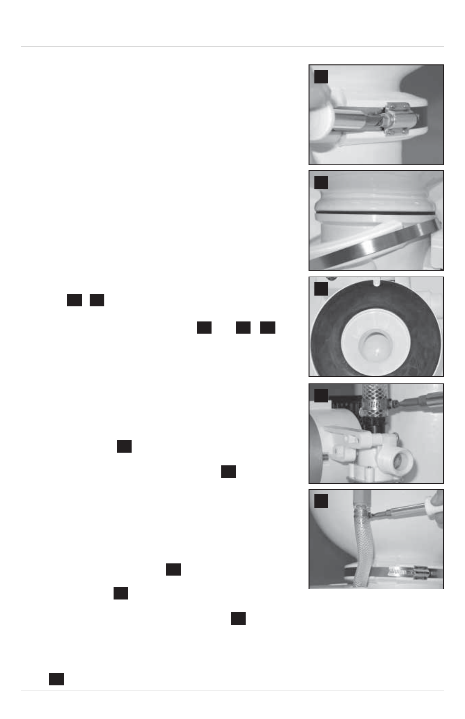
3. (Optional) If macerator pump and base must be positioned at
an angle so that toilet bowl does not face in correct direction,
the upper bowl can be rotated to the proper position:
a. Loosen compression band (
9
) just enough to slip down
past lower plastic clamp, and remove upper and lower
plastic clamps (
10
).
b. Lift bowl. Make sure notch in black rubber gasket sits around shallow pin on toilet base and
remains centered between bowl and base (
11
). Rotate bowl to desired position, then set it
down on gasket.
c. Re-position plastic clamps and compression band between upper bowl and base. Join
clamps together at front of toilet bowl (there will be a space between the clamps behind the
bowl). With compression band screw positioned on a clamp (not in gap between clamps)
(
9
), tighten compression band to 65 in.-lbs.
9
12
13
10
11
Dometic MasterFlush