Optional adjustable level indicator cap, Probe switch adjustment, Optional universal flange – SeaLand TankManager User Manual
Page 6
6
OPTIONAL ADJUSTAbLE LEVEL INDICATOR CAP
1. The adjustable level indicator cap is designed for a 3-inch FPT opening. Order the optional universal flange
(SeaLand P/N 230272) if tank is made of rigid material and not a SeaLand holding tank.
2. Loosen the compression nuts on the adjustable probes and install the cap into the tank. Slide the # probe
tubing down until the float touches the bottom of the tank. Tighten #1 probe compression nut and mark the
tubing at the top of the nut with a pen or pencil. Do not cut the tubing at this mark. Loosen the compression
nut, slide the tubing up, and carefully cut the tubing 5/8-inch (4 mm) below the mark without damaging
the switch wires. (NOtE: tubing should only be cut with a roller guide tubing cutter (used for brass or copper
tubing) to prevent damaging the float switch wires.) Pull the wires through the black wire cover and push the
tubing down into the compression nut until the black wire cover touches the compression nut.
3. Remove the cap from the tank and adjust the #2 probe for /2 full level. tighten the compression nut and cut
the tubing off 3/8-inch (0mm) above the compression nut without damaging the switch wires. Slip the black
wire cover on to the top of the tubing.
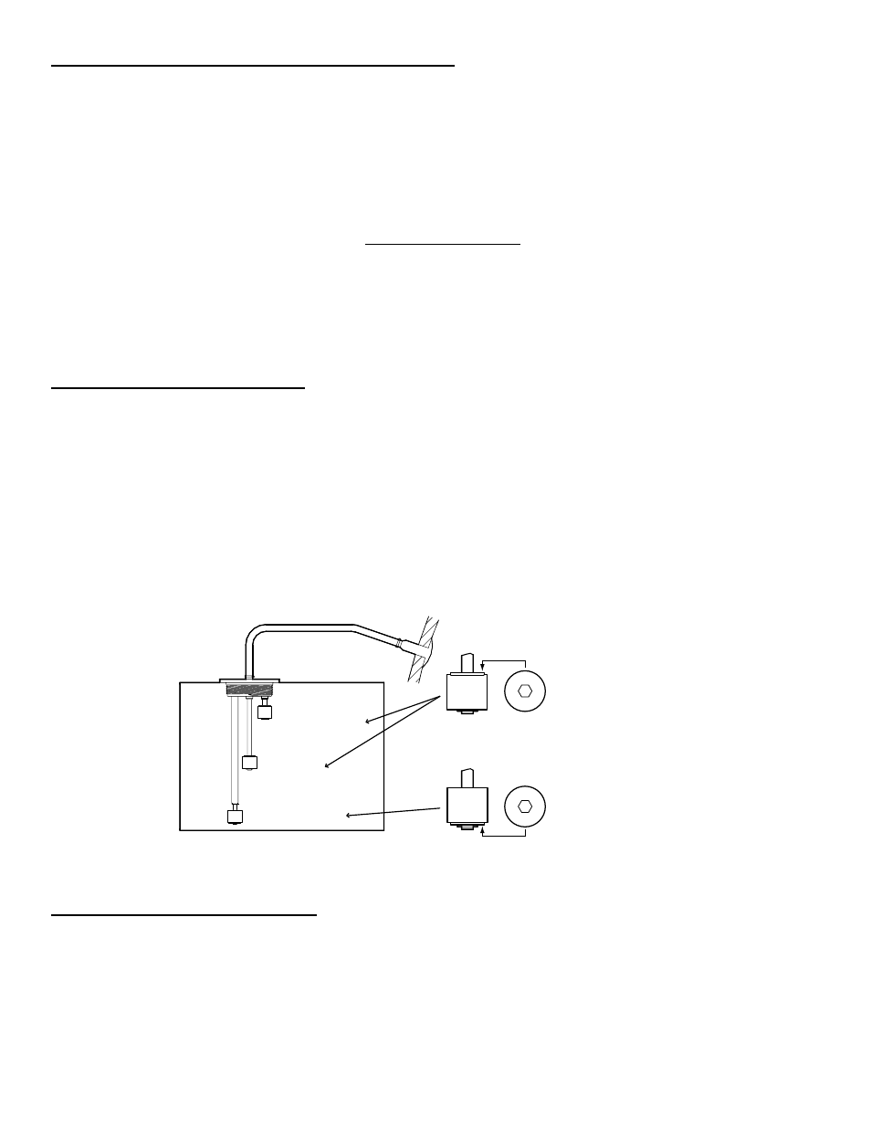
5. For the TankManager system to work properly, the Low float (#1 probe) must be positioned with the recessed
shoulder, white band, or the letters “NO” at the bottom. The Mid and Full floats (#2 and #3 probes) must be
positioned with the recessed shoulder, white band, or the letters “NO” up (see Figure 1). If the float must be
repositioned, remove the C-clip from the switch body, flip the float 180 degrees, and replace the C-clip.
PRObE SWITCH ADJUSTMENT
1. It is important that the Low and Mid floats of the TankWatch 4 level indicator cap are adjusted for the
tankmanager to operate properly.
2. The #1 probe must be positioned just slightly above the diptube opening or tank outlet. If this float is posi-
tioned too low, the discharge pump will not shut off properly. this is because the sewage level in the tank will
never drop below the level of the tank outlet. If the Low float is adjusted below this critical level, it will never
disengage and turn off the discharge pump.
3. The location of the #2 probe is entirely up to the installer. The higher the float is positioned, the longer the
discharge pump cycle will be. We recommend locating the float approximately 4 inches above the #1 probe.
If either a longer or shorter pump cycle time is preferred, adjust the #2 probe accordingly. However, the Empty,
Low and mid readings may not be true after adjustment. For example, if the #2 (mid) probe switch is raised
several inches in order to obtain a longer pump cycle time, the mid light will actually signal that the tank is slightly
fuller.
OPTIONAL UNIVERSAL fLANGE
. Find and mark the top center of the tank.
2. Cut a 4 /6-inch (03 mm) diameter hole in the top center of the tank.
3. Slip the flange into the hole and mark the location of the five mounting holes.
4. Drill the five mounting holes with a ¼-inch (6 mm) drill bit.
5. Remove the flange, clean all oils, grease and dirt from the mounting surface and allow to dry.
6. Apply liberal amounts of silicone rubber adhesive to the mounting surface and the underside of the flange.
7. Insert the gasket into the flange and align with the five mounting holes.
8. Secure the flange with the screws, nuts and washers provided.
9. Install the float switch cap.
figure 1
VENt LINE
N
O
WASTE TANK
(black and gray water)
N
O
mID/FULL
FLOAtS
PROBE #
(Empty or Low level)
PROBE #2
(mid level)
PROBE #3
(High or Full level)
EMPTY/LOW
FLOAt
“NO”,
recessed
shoulder, or
white band
up
“NO”,
recessed
shoulder, or
white band
down