SeaLand Universal Level Indicator User Manual
SeaLand Hardware
1
SPECIFICATIONS
MOdEl INFOrMATION
Part Number
description
385311253
Universal Level Indicator Kit, 12-inch (305 mm)
385311254
Universal Level Indicator Kit, 24-inch (610 mm)
Maximum Allowable Current:
12 Volts DC:
1.6 amps
24 volts DC:
.83 amps
INSTAllATION INSTrUCTIONS
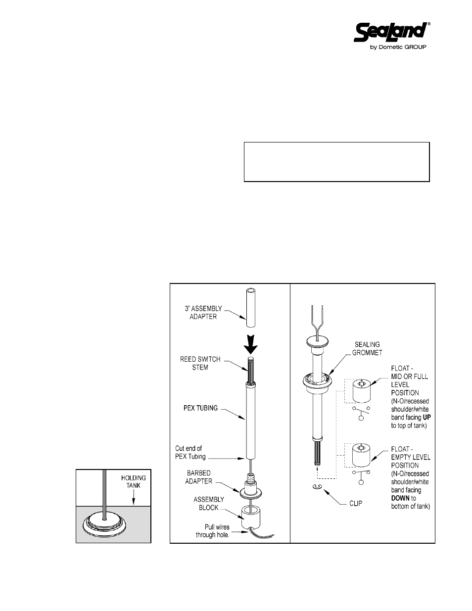
1. Cut PEX Tubing to desired length.
dO NOT CUT wIrES INSIdE TUbINg.
2. Thread wires through Barbed Adapter and Assembly Block (see fig.1). Make sure wires go through hole
in bottom of Assembly Block.
3. Slide 3" Assembly Adapter over Reed Switch Stem, and place cut end of PEX Tubing on top of Barbed
Adapter.
4. Secure PEX Tubing onto Barbed Adapter by carefully hammering down on 3" Assembly Adapter.
5. Turn assembly right-side up (see fig. 2). Slide Sealing Grommet onto PEX Tubing with larger, printed side
of grommet facing up. Allow
Sealing Grommet to remain
loose around PEX Tubing.
6. Position Float for desired
function. Slide Float onto
Reed Switch Stem and
secure in place with Clip.
7. Drill or use existing 1-1/8-
inch (28.6 mm) dia. hole in
holding tank for insertion
of level indicator assembly.
Lower Float and PEX
Tubing into tank. Push
Sealing Grommet into hole
so that no gaps show on
top of tank. Push top part of
assembly (Barbed Adapter)
down into Sealing Grommet
until it is flat against top of
grommet (see below).
8. Connect wires as they were previously connected.
Universal level Indicator Kit
Installation Instructions
dometic Corporation - Sanitation division
13128 State Rt. 226, P.O. Box 38
Big Prairie, OH 44611-0038 USA
330-439-5550
1-800-321-9886 • Fax: 330-496-3097
Figure 1
Figure 2
® Registered; ™ Trademark of Dometic Corporation
© Dometic Corporation
600345176 02 06/13
TYPiCAL BLACKWATer TANK
FLOAT POSiTiONS
NOTE: Float switches will have either a recessed shoulder
on one end, a white band around one end, or the letters
"NO at one end and "NC" at the opposite end. Position
Float according to directions below.