Rating plate 2, Serial no. 2, Rating plates and serial no – Reznor MAPSII Series Parts Manuals User Manual
Page 3: Serial no. decoding
P-MAPSII, P/N 271467R1, Page 2
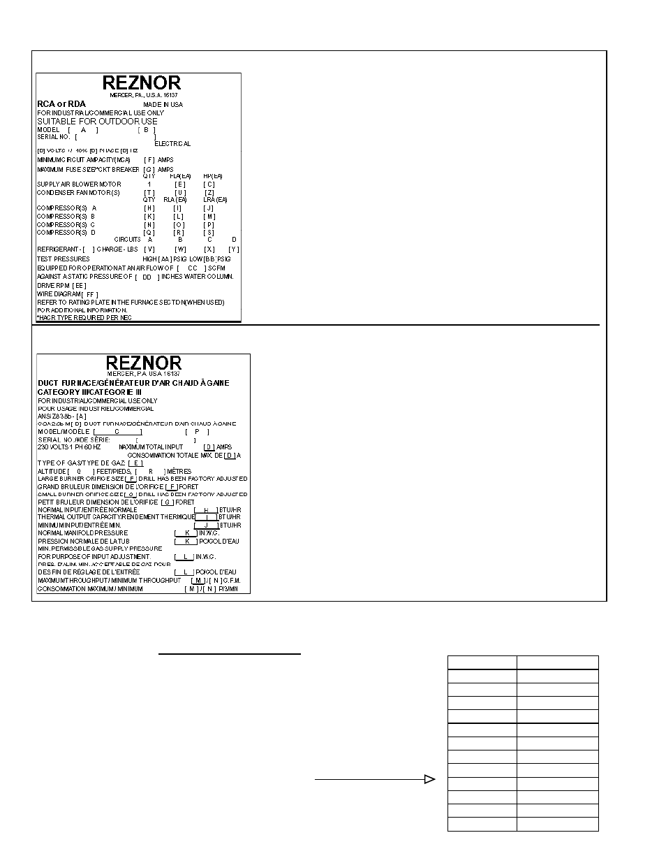
Sample of System Rating Plate (applies to all models)
System Rating Plate Key:
A = Model
B = Manufacturing Date (Month/Year)
C = Blower Motor HP
D = Volts/Phase/Hertz
E = Full Load Amps of Blower Motor
F = Minimum Circuit Ampacity
G = Maximum Fuse Size
H = Quantity - Compressor A
I = Rated Load Amps of Compressor A
J = Locked Rotor Amps of Compressor A
K = Quantity - Compressor B
L = Rated Load Amps of Compressor B
M = Locked Rotor Amps of Compressor B
N = Quantity - Compressor C
O = Rated Load Amps of Compressor C
P = Locked Rotor Amps of Compressor C
Q = Quantity - Compressor D
R = Rated Load Amps of Compressor D
S = Locked Rotor Amps of Compressor D
T = Quantity Condenser Fan Motors
Gas Heat Section Rating Plate Key:
A = ANSI Standard Date
B = CSA Standard Date
C = Model No.
D = Amps
E = Type of Gas (natural or propane)
F = Orifice Size of Large Burner
G = Orifice Size of Small Burner
H = Normal BTUH Input (sea level)
I = Thermal Output BTUH (sea level)
J = Minimum BTUH Input (sea level)
K = Manifold Pressure
L = Minimum Gas Supply Pressure
M = Maximum Throughput
N = Minimum Throughput
P = Manufacturing Date (Month/Year)
Q = Altitude in Feet
R = Altitude in Meters
U = Rated Load Amps of Condenser(s)
V = Refrigerant Charge (lbs) - Circuit A
W = Refrigerant Charge (lbs) - Circuit B
X = Refrigerant Charge (lbs) - Circuit C
Y = Refrigerant Charge (lbs) - Circuit D
Z = Condenser Fan Motor HP
AA = Test Pressure High (psig)
BB = Test Pressure Low (psig)
CC = SCFM Airflow
DD = External Static Pressure (“ w.c.)
EE = Drive (Option AM)
FF = Wiring Diagram No.
Sample of a Gas Heat Section Rating Plate (applies to Models RDCA and RDDA)
Rating Plates and Serial No.
Serial No. Decoding
Decoding a System Serial No.
Serial No. Sample: 3 BDG 553 EL 08 N 78 8B
Elements of No.: 1| 2 | 3 | 4 | 5 |6| 7 | 8
Elements 1-5 apply to all models.
Elements 6-7 apply to models with gas heat section (RCDA and RDDA).
K
ey: 1 = Phase (1 or 3)
2 = Date CODE (See table on page 3.)
3 = Consecutive number
4 = Drive (See drive components on pages 14-17.)
5 = Motor HP (See explanation on the right.)
6 = Type of Gas (N = Natural; L = Propane)
7 = Ignition CODE (See Form P-Valves.)
8 = Valve CODE (See Form P-Valves.)
Motor HP
Serial No. Code
1/2
03
3/4
04
1
05
1-1/2
06
2
07
3 (3450 rpm)
08
5 (3450 rpm)
09
7
10
7-1/2
11
10
13
3 (1800rpm)
15
5 (1800rpm)
16
®
®