Damper 20, Arm 20, Damper components 20 – Reznor MAPSII Series Parts Manuals User Manual
Page 21: Hand quadrant 20, Damper motor 20, Potentiometer 20, Pressure null switch 20, Inlet air components (cont’d), Damper components
P-MAPSII, P/N 271467R1, Page 20
Inlet Air
Components
(cont’d)
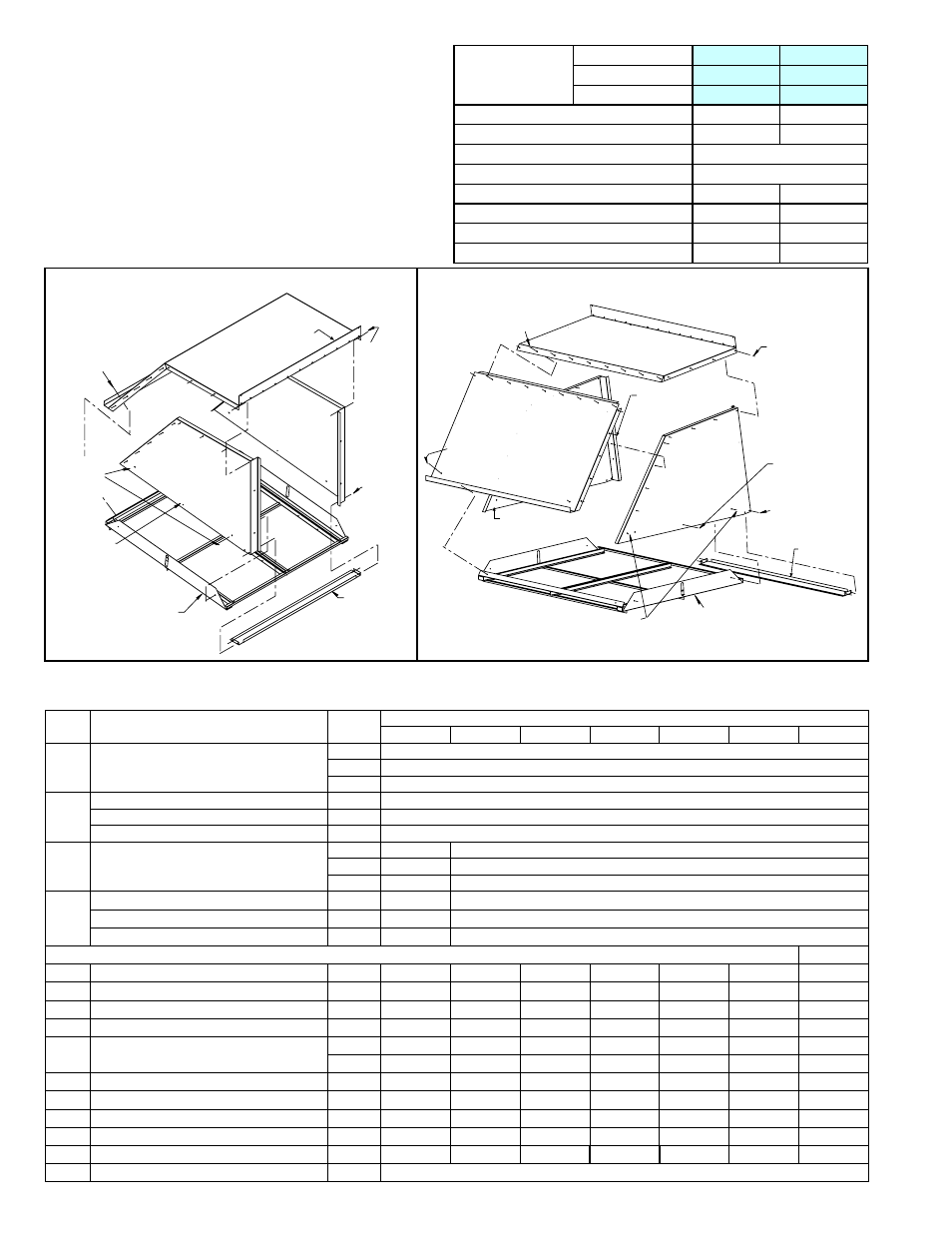
CODE 96 (cont’d) - Outside Air Hood,
Option AS16 and Option AS19
Hood components are listed by cabinet size and option
code. See page 3 for cross-reference of model/size and
cabinet size.
1/2 Sheetmetal
Screws (Qty 2)
P/N 11813
Left Side
Panel,
P/N 194272
3/4
Sheetmetal
Screws
(Qty 2,
1 per side)
P/N 99542
Filter Frame Assy,
P/N 214413 -
Holds four P/N 194903,
18x20x1 permanent
aluminumfilters.
Hood
Bottom
P/N 214415
1/2
Sheetmetal
Screws
(Qty 4 -
2 per side)
P/N 11813
Right Side
Panel,
P/N 194273
1/2
Sheetmetal
Screws
(Qty 18 -
9 per side)
P/N 11813
Hood T
op, P/N 214417
(edge must be
under the cabinet top)
1/2
Sheetmetal
Screws
(Qty 4,
2 per side)
P/N 11813
1/2 Sheetmetal
Screws (Qty 9)
P/N 11813
Hood Top, P/N 214411
(edge must be under the cabinet top)
1/2 Sheetmetal
Screws (Qty 8,
4 per side)
P/N 11813
Top Panel
Slope Section,
P/N 214412
1/2 Sheetmetal Screws
(Qty 10, 5 per side)
P/N 11813
Left Side Panel,
P/N 194272
1/2 Sheetmetal
Screws (Qty 4, 2
per side) P/N 11813
3/4 Sheetmetal
Screws (Qty 2,
1 per side)
P/N 99542
Hood Bottom
P/N 214416
Filter Frame Assembly,
P/N 214414 - holds
(4) 20x25x1 permanent
aluminum filters,
P/N 101610
1/2 Sheetmetal Screws
(Qty 4, 2 per side)
P/N 11813
1/2 Sheetmetal
Screws (Qty 2)
P/N 11813
Right Side
Panel,
P/N 194273
Assembly of Option AS19 Outside Air Hood for
Cabinet A
Assembly of Option AS19 Outside Air Hood for Cabinet B
Description
Cabinet Size
A
B
Hood Option
AS19
AS19
Package P/N
215624
215625
Hood
Top
(1)
214417
(1)
214411
Hood
Top Slope
--
(1)
214412
Hood
Right Side
(1)
194273
Hood
Left Side
(1)
194272
Hood
Bottom
(1)
214415
(1)
214416
Filter Rack Assembly
(1)
214413
(1)
214414
Permanent Aluminum Filter 18 x 20 x 1
(4)
194903
--
Permanent Aluminum Filter 20 x 25 x 1
--
(4)
101610
Damper Components
Damper components are listed by cabinet size and option code. See page 3 for cross-reference by model/size and cabinet size.
CODE Description
Cabinet
Size
By Option Code
AR8
AR11
AR17
AR18
AR23
AR27
AR25
100 Outside Air Damper Frame Assembly
(includes damper CODE 100A)
A
(1)
205051
B
(1)
205052
C
(1)
208109
100A
Outside Air Damper # Cd-36-Mod
A
(1)
205066, 24” X 20”
Outside Air Damper # Cd-36-Mod
B
(1)
205068, 36” X 20”
Outside Air Damper
C
(1)
208368, 49.75” X 25.75”
101 Return Air Damper Frame Assembly
(does not include dampers; see below)
A
--
(1)
205053
B
--
(1)
205054
C
--
(1)
208110
102
Return Air Damper Cd36-Mod
A
--
(1)
205067, 23.5”X 12.38”
Return Air Damper Cd36-Mod
B
--
(1)
205069, 38.5”X 12.38”
Return Air Damper
C
--
(1)
208369 48.875” X 17.25”
Damper Controls:
103 2-Position Motor J/C#M9216-BGC2
A,B,C (1)
159892
--
(1)
159892
--
--
--
--
103 Damper Motor AF24-MFT95-US
A,B,C
--
--
--
(1)
159877
--
--
105 Damper Motor J/C #M9116-Agc-2
A,B,C
--
--
--
--
(1)
159879 (1) 159879
106 Damper Motor, J/C M9206GGC-2
A,B,C
--
--
--
--
--
--
(1)
211417
107 Motor Bracket (not illustrated)
A,B
(1)
207435
--
(1)
207435 (1) 207435 (1) 207435 (1) 207435 (1) 207435
C
(1)
208602
--
(1)
208602 (1) 208602 (1) 208602 (1) 208602 (1) 208602
108 Hand Quadrant, #09250 (not illustrated) A,B,C
--
(1)
103502
--
--
--
--
--
109 Hand Quadrant Bracket (not illustrated) A,B,C
--
(1)
175248
--
--
--
--
--
110 Potentiometer, Manual 112894 Fa
A,B,C
--
--
--
(1)
16110
--
--
--
111 Pressure Null Switch #1640-0 Dwyer
A,B,C
--
--
--
--
(1)
88052 (1) 88052
--
112 Damper Arm, M/H 26026N
A,B,C (1)
12635 (2) 12635 (1) 12635 (1) 12635 (1) 12635 (1) 12635 (1) 12635
113 Ball & Socket, M/H 27518
A,B,C
(2)
12636