Ype of valve originally supplied, Ii models rdca/rdda – Reznor Valves Parts Manuals User Manual
Page 20
Form P-VALVES, P/N 263995R4, Page 20
*Model
Series
Sizes
Gas
Original Valve Code
(see Serial No. on
Furnace Rating Plate)
P/N's (and Codes) of Valves that can be used as Functional
Replacements for the Mechanical Modulation Valve (two replace-
ment valves are always required)
X/RX
75-350**
Natural N1
P/N 131453 (R7) and solenoid valve, P/N 88242 (J/C #H91LG-8)
X/RX
400
Natural N1
Replacement is not available.
X/RX
75-400
Propane N3
P/N 131454 (R9) and solenoid valve, P/N 88242 (J/C #H91LG-8)
RG/RP/SSC
75-225
Natural N1, N7, N8, P6, Q7
P/N 131453 (R7) and Replacement Kit P/N 221634
RG/RP/SSC
250-400
Natural N1
P/N 131455 (R8) and Replacement Kit P/N 221526
RG/RP/SSC 250-350**
Natural N8, N9, P6, Q5
P/N 131453 (R7) and Replacement Kit P/N 221526
RG/RP/SSC
400
Natural N9, Q5
Replacement is not available.
RG/RP/SSC
75-225
Propane N3, N5, N6, Q9
P/N 131454 (R9) and Replacement Kit P/N 221634
RG/RP/SSC
250-400
Propane N3
P/N 131456 (S1) and Replacement Kit P/N 221526
RG/RP/SSC
250-400
Propane N6
P/N 131454 (R9) and Replacement Kit P/N 221526
ADF/ADFH
300-1200 Natural or
Propane N1, N9
P/N 131455 (R8) and Replacement Kit P/N 221526
*Only duct furnace model identification of indirect-fired units appears here and on the rating plate. If the duct furnace is part of a
Model XE, RGB, RPB, PAK, PGBL, RGBL, RPBL or SSCBL packaged furnace/blower system, valve replacement requirements
are the same as for the component duct furnaces.
**On duct furnace Sizes 300 and 350, dual functional replacement valves require a minimum gas supply pressure of 7" w.c.
31
Special 1/2" H91EG valve drilled 1/8", used as low stage valve on Model XL60,
also used a standard 1/2" H91EG as high stage.
32
Special valve furnished by Bell Telephone.
33
Serial No. Codes O1, O2, O3, O4, and O5 apply to units manufactured from 5/90 to
12/90. Beginning with 1/91, these codes were changed to P1, P2, P3, P4 and P5.
34
When the current inventory of this valve is depleted, a SINGLE mechanical modu-
lation replacement valve WILL NO LONGER BE AVAILABLE.
WARNING: Do not replace an existing mechanical modula-
tion valve with mechanical modulation valve Code R7, R8,
R9, or S1 ONLY. To do so will result in an unsafe condition.
Replacement requires dual functional valves. A mechanical modulation valve plus
either a solenoid valve or a single-stage valve depending on the application are
required.
Field-furnished pipe nipples will be required to adapt the manifold for the two
replacement valves. Install valves in series with single-stage or solenoid valve first
and mechanical modulation valve second in the gas stream.
The chart below lists dual functional replacement valves by model/size/gas type
combinations. Valves are available for most sizes. When functional replacement
valves are not available from Reznor, contact valve manufacturer concerning avail-
ability of a functional replacement.
35
Manifold arrangement also includes a single-stage solenoid valve,
P/N 88242, J/C
#H91LG-8.
36
(H)(C)X(E) and (H)(C)RX(E) units mfgd prior to 11/86 must add lighter tube carry-
over kit.
37
Original valve includes an ECO adapter that is not field replaceable.
38
For replacement of ECO adapter only, see page 26.
39
Do not use replacement valve on units with G29 or G33 ignition controls
40
ECO adapter on replacement valve is not field replaceable.
41
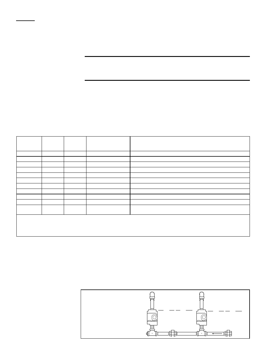
AG55, 3:1 gas control manifold illustrations identifying valves by their location.
Gas Valve controlling
gas flow to 1/3 burner
Size
Gas P/N
Code
100-400 Nat 196980 Z7
100-400 Pro 196982 Z9
Gas Valve controlling
gas flow to 2/3 burner
Size
Gas P/N
Code
100-300 Nat 196980 Z7
100-300 Pro 196982 Z9
350-400 Nat 196981 Y3orZ8
350-400 Pro 196983 Y5or1A
To 2/3 Burner
(STAGE 2)
To 1/3 Burner
(STAGE 1)
Both Valves; Full Burner (STAGE 3)
Manifold Arrangement
for Gas Control
AG55 on Gas Heat
Section Sizes 100-400
in MAPS
®
II Models
RDCA/RDDA
NOTES (cont'd) for
pages 11-18, "T
ype
of Valve Originally
Supplied"