Reznor R6GN Option - Installation - Economizer User Manual
Page 6
Roof top Sys tems, Inc.
2405 McIver Lane
Car roll ton, Texas 75006
Phone (972) 247- 7447
Fax
(972) 243- 0940
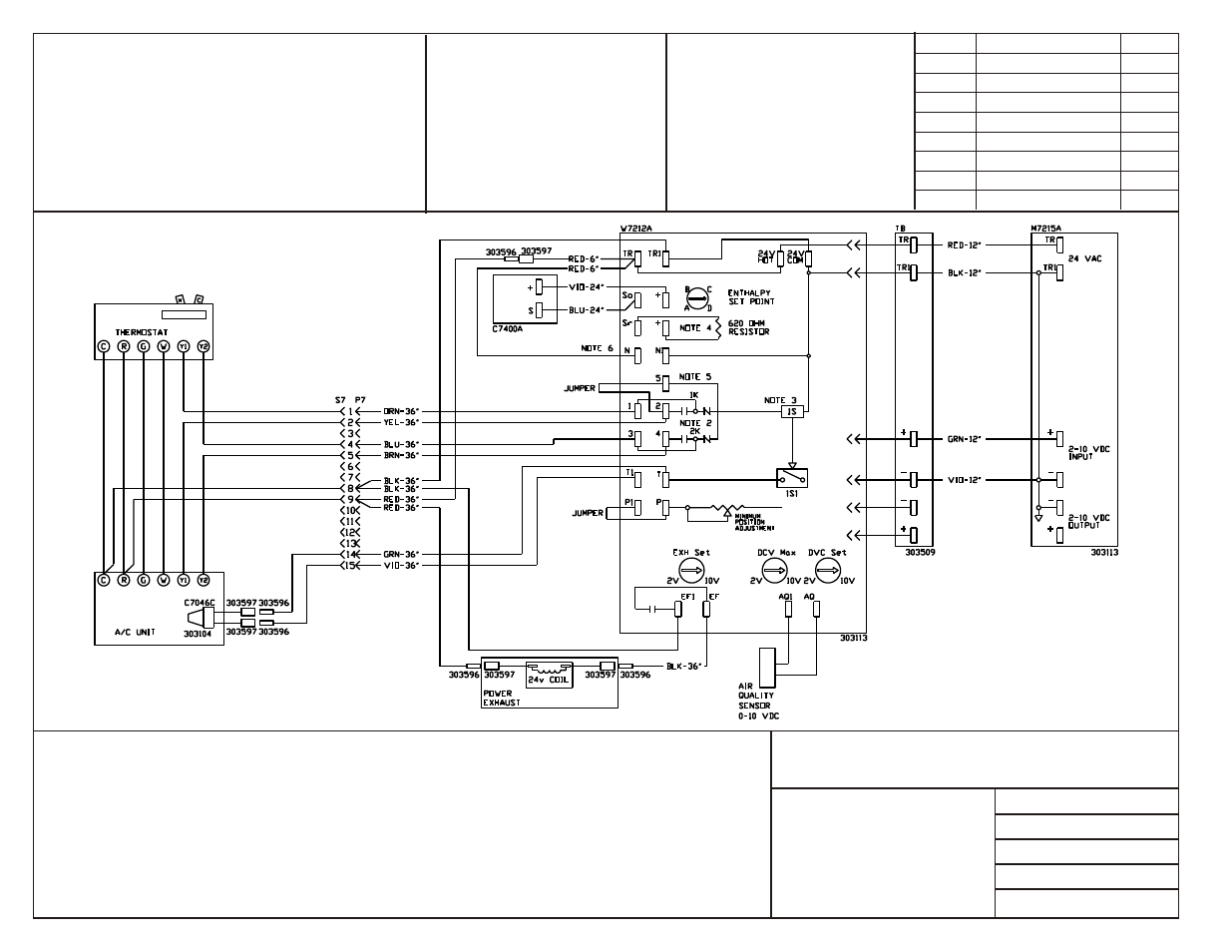
Mod u lat ing Economizer
R4GM 150-180
Notes:
1. Unit wir ing shown as ref er ence only. Check unit wir ing for ac tual unit wir ing.
2. Re lays 1K and 2K ac tu ate when the Out door Air Enthalpy is higher than the enthalpy set point A-D
on the W7212A Logic Module.
3. 1S is an elec tronic switch which closes when pow ered by a 24 VAC in put.
4. Fac tory in stalled re sis tor should be re moved only if C7400 Dif fer en tial Enthalpy Sen sor is added.
5. Y2 must be en er gized for Stage 1 com pres sor to op er ate dur ing economizer operation.
6. "N" ter mi nal used for oc cu pied mode. Re move jumper when night set back con trol uti lized. 24v
must be ap plied for oc cu pied mode op er a tion.
Date: De cem ber 19, 2007
Su per cedes: 06-30-06
Drawn by:
Unit # 47-364-10
Dia gram# 4736410W
HARNESS DETAIL
E# = WIRE END DESIGNATION
E2
STUD #6 18 Ga. Wire
E3
Female ¼ Quick Disc.
E4
Male ¼ Quick Disc. Insul
E6
Wire Nut Size 73B
HAR NESS ENDS AT
(P7) ECONOMIZER
CONNECTOR & CONTACT CONFIGURATION
P7 - (303908/303903) PLUG & (303912) PIN
WIRE COLOR CODE
BLK
Black
BLU
Blue
BRN
Brown
GRN
Green
ORN
Orange
RED
Red
VIO
Violet
YEL
Yellow
WHT
White
COMPONENT CODE
Economizer
C7046C
Mixed Air Sensor
C7400A
Fresh Air Sensor
M7215A
Damper Actuator 24V
P7/S7
Plug/Cap Economizer
TB
Terminal Board
W7212A
Logic Module
Re vi sion
Change
Date
A
Changed R & C around
06-30-06
B
Changed wir ing diagram
12-18-07