See unit wiring diagram for connections at s1, Har ness ends at (p1) e cono mizer plug – Reznor R6GP Option - Installation - Economizer - Lt Commercial User Manual
Page 9
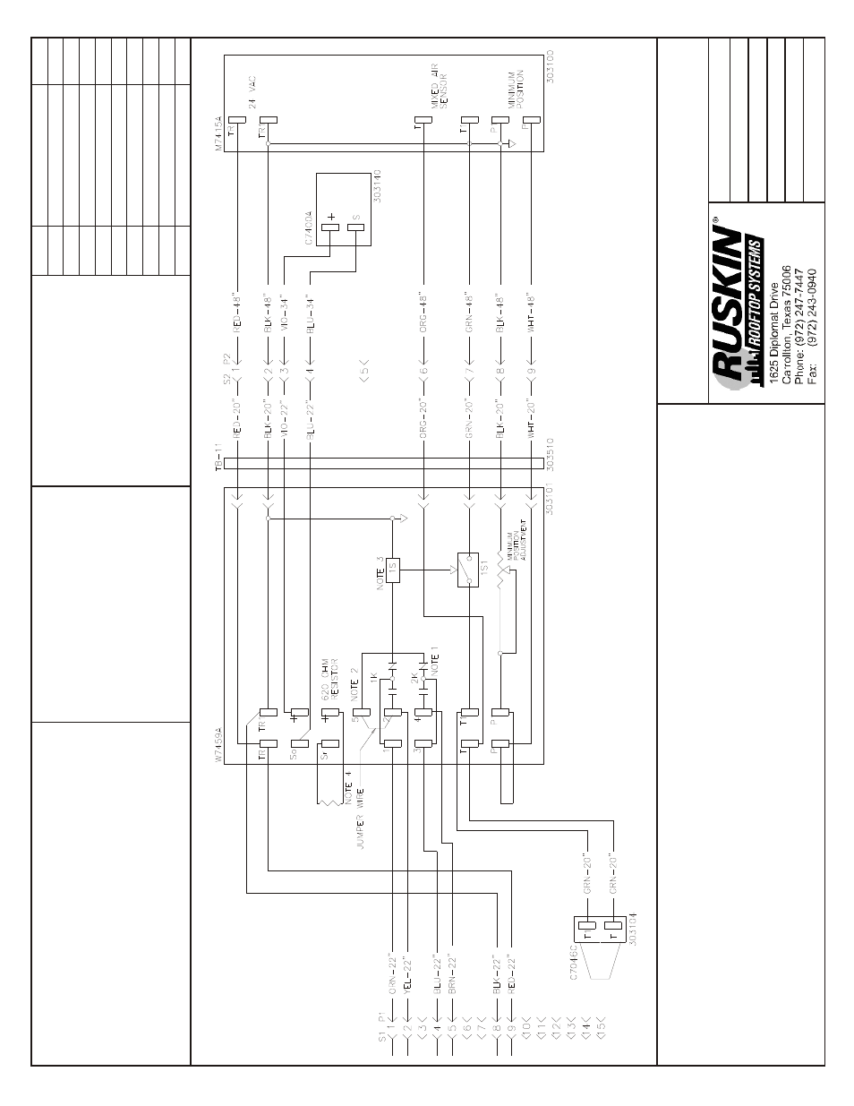
Mod u lat ing
Economizer
Q5SN / Q6SP
090-120
P6 / R6 120 (559374)
Notes:
1.
Y2 must
be en
er
gized for S
tage 1 com
pres
sor to op
er
ate dur
ing economizer
op
er
a
tion.
2.
Re
lays 1K and 2K ac
tu
ate w
hen the out
door air ent
halpy is higher than the enthal
py set point A-D
on the the W
7459A Logic Mod
ule.
3.
1S is an elec
tronic s
w
itch w
hich closes
w
hen pow
ered by a 24 VAC in
put.
4.
Fac
tory in
stalled 620 O
hm, 1 W
att,
5% re
sis
tor should be r
e
moved only w
hen a sec
ond C7400
Enthalpy Sen
sor is added t
o SR and + f
or dif
fer
en
tial enthal
py con
trol.
Date: J
une 22, 2010
Supersedes:
06-07-10
Draw
n by: MGL
Unit #: 47-
314-11
Di a gram#:
4731411W
Ap proved
by:
WIRE COLOR CODE
BLK
Black
BLU
Blue
BRN
Brow
n
GRN
Green
ORN
Orange
RED
Red
VIO
Violet
WHT
White
YE
L
Y
ellow
COMPONENT CODE
C7046C
Mixed Air Sensor
C7400A
Fresh Air Sensor
M7415A
Damper Actuator 24V
P1/S1
Plug/Cap Economi
zer
P2/S2
Plug/Cap Economi
zer
TB-11
Terminal Board
W7459A
Logic Module
Re vi sion
Change
Date
A
Changed mix
ed air sensor
11-07-07
B
Changed w
ire lengths
06-07-10
C
Added S2/P2 plugs bac
k in
06-18-10
HA
RNESS DETA
IL
E# = WIRE END DESI
GNATI
ON
E2
STUD #6 18 Ga. Wire
E3
Fema
le ¼ Q
uick Disc.
E4
Male ¼ Q
uick Disc. I
nsul
E6
Wire Nut Size 73B
HAR
NESS ENDS AT
(P1) E
CONO
MIZER
PLUG
See Unit Wiring Diagram for Connections
at S1
CONNECTOR & CONTA
CT CONFIGURA
TION
P1 - (303908) PLUG & (303912)
PIN
S2/P2 - (303903/303904) CA
P/PLUG & (303913/303912) SOCKET/PIN