Reznor R6GP Option - Installation - Economizer - Lt Commercial User Manual
Installation instruction
INSTALLATION
INSTRUCTION
INSTALLATION INSTRUCTIONS FOR
559374
ECONOMIZERS USED WITH Q5SN / Q6SP 090-120
P6 / R6 120 UNITS
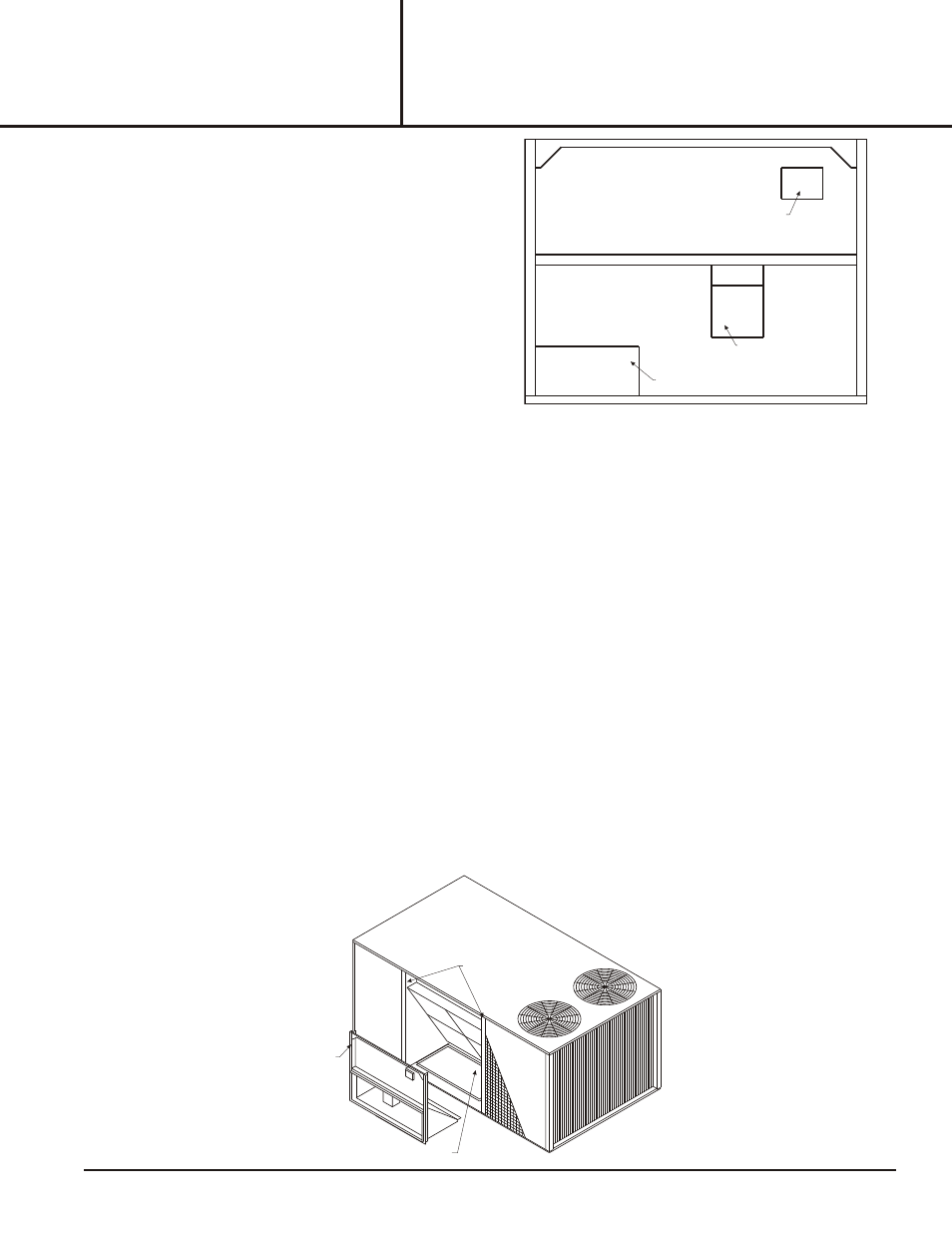
Fig ure 1
ENTHALPY SENSOR
CONTROL PACKAGE (STEP 3)
DAMPER MOTOR
MULLIONS
RETURN AIR OPENING
INSERT THE SIDE FLANGES INTO
THE UNIT STANDING SEAMS
Figure 2
FORM# 571C-0411 (571C-0610)
1
I - SHIP PING AND PACK ING LIST
Package 1 of 1 contains:
1 - Economizer Assembly
1 - Fresh Air Hood w/ Filter
1 - Control Package
1 - Barometric Relief Hood
1 - Filter Access Panel
2 - Wire Nut (For Mixed Air Sensor)
16 - #10 x ½ x 16 Hex Tec
Check contents for shipping damage. Contact the last carrier
immediately if any shipping damage is found.
II - AP PLI CA TION
Economizers are used with Q5SN/Q6SP/P6/R6 units for automatic sensor-controlled introduction of outdoor air into the
system through an electro-mechanically controlled damper. Outdoor air is mixed with the buildings return air to
economically improve indoor air quality and aide in reducing energy costs.
Economizer slides into horizontal return air opening. Mixed air sensor, TB11, and enthalpy control board relay are shipped
in economizer and must be relocated to the unit's filter section. Intake and exhaust hoods are packaged with economizers
and installed according to instructions below.
III - ECONOMIZER IN STAL LA TION
1.
Disconnect all power to unit.
2.
Cut and discard wire tie securing wire bundle to the damper motor
Important - DO NOT cut other wires. Inspect for damaged connections or loose wires.
3.
Remove box of controls to be installed over the assembly containing the logic control board and mixed air sensor. See
Figure 1.
4.
Remove from box the logic control board and wire bundle. Cut wire tie securing the bundle of wires to logic control
board and mixed air sensor.
5.
Locate S1, the unit's economizer connection and remove the installed dummy plug. See Figure 3.
6.
Connect economizer jack S2 to economizer plug P2 on the economizer assembly.
7.
Route wiring to the right side of the economizer and slide it into the unit. Insert economizer side flanges into the unit
standing seams. Using existing screws from bottom of discarded panel to secure economizer bottom flange to unit.
See Figure 2.