Installation instruction, Down flow application, Horizontal application – Reznor R6GP Option - Installation - Economizer - Lt Commercial User Manual
Page 2
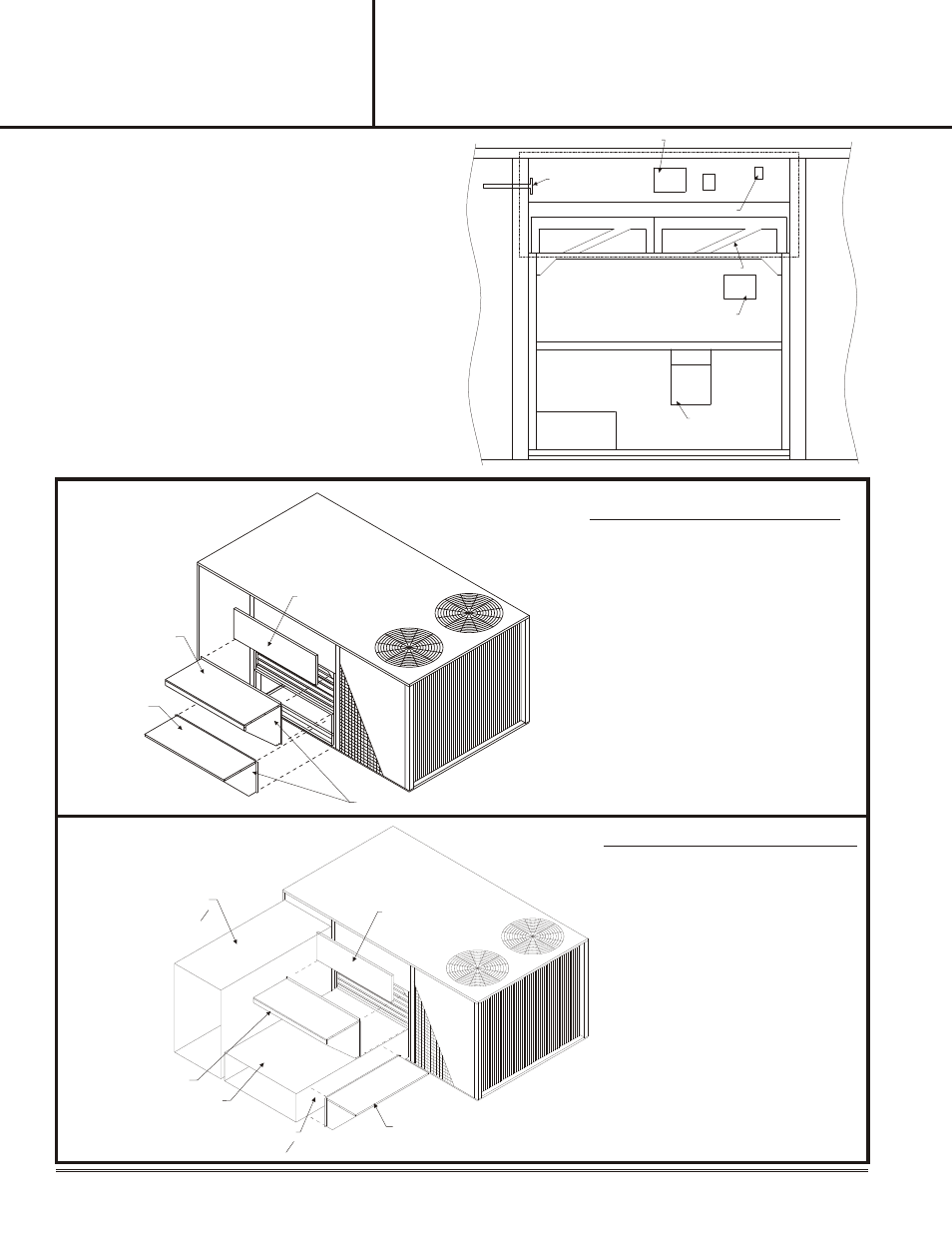
TB11 BOARD AND LOGIC CON TROL
FIL TERS
INTAKE AIR
EXHAUST AIR
Figure 3
DAMPER MOTOR
ENTHALPY SENSOR
S1 UNIT JACK
MIXED AIR SENSOR
DOWN FLOW APPLICATION
Figure 4
FILTER ACCESS
SCREW TO SIDE MULLIONS
FRESH AIR HOOD
BAROMETRIC
RELIEF HOOD
12. Install barometric relief hood in front
of exhaust air opening.
13. Install fresh air hood in front of intake
opening.
14. Slide filter access panel underneath
top of unit and secure to mullions.
a.
For heatpump units refer to
Section IV before restoring the
unit power.
15. Restore power to unit and check for
proper damper operation (See
System Check section).
12. Install barometric relief hood to
return duct over the opening in
duct.
13. Install fresh air hood in front of
intake opening.
1 4 . S l i d e f il t e r a c c e s s p a n e l
underneath top of unit and
secure to mullions.
a.
For heatpump units refer to
Section IV before restoring
the unit power.
15. Restore power to unit and check
for proper damper operation
(See System Check section).
BAROMETRIC RELIEF HOOD
FRESH AIR HOOD
Figure 5
8.
Position logic control board in filter access area as
shown in Figure 3. Secure control board with two
#10-16 x ½ screws.
9.
Insert mixed air sensor tube through the mounting
hole into the supply air compartment. Secure using
two #10-16 x ½ screws. See Figure 3.
10. Connect economizer plug P1 to unit jack S1 on units
economizer control panel.
11. Verify that wire harnesses are secure and will not
interfere with economizer vane and linkage
operation, or with a filter change out
Note: Leave unit dummy plug (from Step 5) in the
unit control panel for later use if the
economizer needs to be by passed.
FILTER ACCESS
INSTALLATION
INSTRUCTION
INSTALLATION INSTRUCTIONS FOR
559374
ECONOMIZERS USED WITH Q5SN / Q6SP 090-120
P6 / R6 120 UNITS
NOTE:
FOR THIS APPLICATION, HORIZONTAL
DUCT KIT #547881 IS REQUIRED.
HORIZONTAL APPLICATION
2
CUT HOLE
559374 - 31" x 18
3
8
SUPPLY DUCT
30 x 16
3
8
RETURN DUCT
31 x 18 ¾