Installation instruction – Reznor R6GP Option - Installation - Economizer - Lt Commercial User Manual
Page 7
7
INSTALLATION
INSTRUCTION
INSTALLATION INSTRUCTIONS FOR
559374
ECONOMIZERS USED WITH Q5SN / Q6SP 090-120
P6 / R6 120 UNITS
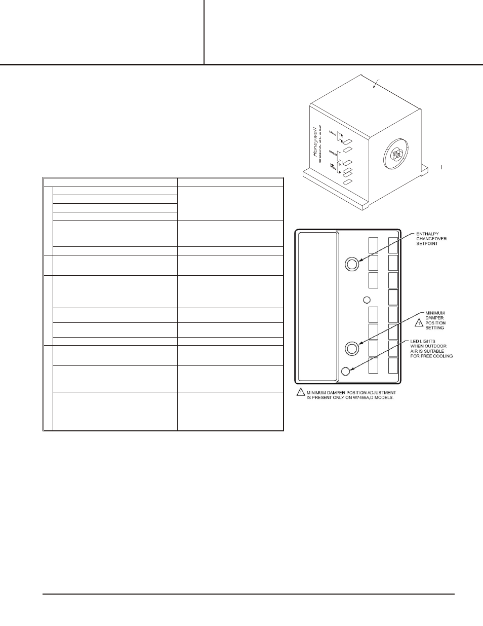
Figure 9 - W7459A
Figure 8 - M7415A
DAMPER ACTUATOR
Check out Procedure
Proper Response
1. a. Dis con nect power at TR and TR1.
----
b. Dis con nect Jumper P to P1.
c. Jumper TR to 1.
d. Jumper T1 to T.
e. If con
nected, re
move C7400 Solid State
Enthalpy Sen
sor from ter
mi
nals SO and +.
En sure fac tory-in stalled 620 ohm re sis tor is
connected to terminals SR and +.
LED is off.
f. Apply power (24 Vac) to terminals TR and TR1.
Motor is in closed position.
2. a. Disconnect factory-installed 620 ohm resistor
from terminals SR and +.
LED turns on (A model only, for D model,
go to step 3).
Motor drives toward open.
3. a. To simulate high and low enthalpy (single
enthalpy sensor), reconnect factory- installed
620 ohm resistor from terminals SR and +.
Connect 1.2K ohm 4074EJM Checkout
Resistor across terminals SO and +
----
b. Turn enthalpy setpoint potentiometer to "A".
LED turns on, indicating low enthalpy.
Motor drives toward open.
c. Turn enthalpy setpoint potentiometer to "D".
LED turns on, indicating high enthalpy.
Motor drives toward closed.
d. Disconnect the 1.2K ohm checkout resistor.
----
4. a. To verify sensor operation, reconnect the + lead
of outdoor enthalpy sensor to the + terminal of
W7459
----
b. Connect a DC milliammeter between terminal
SO of the W7459A and terminal S of the
enthalpy sensor. (Positive meter lead to
terminal S of the enthalpy sensor.)
Milliammeter indication is between 3 and
25 mA if sensor is operating properly.
If milliammeter indicates zero, the sensor
may be wired backwards.
c. When using differential enthalpy, check the
return air enthalpy sensor by connecting a DC
milliammeter between terminal SR of the
W7459A and terminal S of the return air
enthalpy sensor. (Positive meter lead to
terminal S of the enthalpy sensor.)
Milliammeter indication is between 3 and
25 mA if sensor is operating properly.
If milliammeter indicates zero, the sensor
may be wired backwards
CHECK OUT AND TROU BLE SHOOT ING
Check the W7459 for proper operation. Table 1 describe how to
simulate various environmental conditions. Make necessary minor
adjustments to the minimum position until desired operation is
obtained.
If the economizer system does not operate properly, check individual
components of the system according to the instructions provided with
each device.
If the other components operate properly when disconnected from the
W7459, but the system (as a whole) does not, replace the W7459.