Removing the pressure gauge u-tube manometer, Completing the conversion, Figure 2. two-stage white rodgers gas valve – Reznor R6GN Option - Installation - LP Conv Kit User Manual
Page 5
5
NOTE 2: The unit firing rate should be inspected for each
installation as described in these instructions. The manifold
pressure may be different than the factory setting. If the
determination of the actual unit firing rate cannot be made with
quality instruments, then the manifold pressure should be set to
the factory setting shown on the unit rating label for installations
between 0 & 2,000 ft.
White Rodgers Gas valve Adjustment
(12 1/2 - 15 Ton Units):
1. Remove the protective cap from the top of the High fire gas
valve regulator as shown in the manufacturers instructions.
2. Set the manifold pressure to the factory settings, as shown
on the unit rating label – or to the correct manifold pressure
setting to obtain the correct firing rate.
NOTE: Turn the adjusting screw clockwise to increase pressure
or counterclockwise to reduce pressure. To prevent the screw
from backing all the way out from the valve, turn the screw slowly.
3. Replace the protective cap over the adjustment screws and
tighten.
NOTE: The unit Low firing rate (Stage 1 only) should be approx.
65% of the unit High firing rate. (Stage 1 & 2) See Table 2.
From example 1 (page 3): The furnace high fire rating of 129,000
Btuh reduced for 4,000 ft. elevation, would have a low fire rating
of 84,000 Btuh, or 0.65 x 129,000 Btuh.
4. Inspect the unit low firing rate in the same manner described
in the instructions for Verifying & Adjusting Firing Rate section
(Page 4).
5. Use the same procedure for the High fire adjustment described
in steps 1-3 above to adjust the Low fire manifold pressure. If
the firing rate cannot be determined, set the low fire manifold
pressure to the factory setting as shown on the unit rating
label, or refer to table 4.
REMOVING THE PREssURE GAUGE
u-TuBe mANOmeTeR
After the manifold pressure has been properly adjusted, the
pressure gauge or U-tube manometer must be removed from
the gas valve.
1. Turn the thermostat to its lowest setting.
2. Shut OFF the main gas supply to the unit at the manual shut-
off valve, located outside of the unit.
3. Shut OFF all electrical supplies to the unit.
4. Remove the manometer adapter from the gas valve and
replace it with the 1/8” NPT manifold pressure plug removed
earlier. Verify the plug is sealed tightly and not cross threaded.
5. Turn ON all electrical power to the unit.
6. Turn ON the main gas supply to the unit at the manual shut-
off valve, located outside of the unit.
COMPLETING THE CONVERsION
1. For all (*)R4(M,N) or R6GN-150 / 180 conversions to LP gas,
affix the conversion warning label (#703935) provided in the
kit to the outside of the units louvered burner access panel.
Next, affix the conversion information label (#710005) over
the Natural Gas warning label. Each label shall be prominent
and visible after installation.
2. Affix the gas valve manufactures labels to the valve as
described in the manufactures instructions.
3. Replace the unit’s louvered burner access panel.
4. Run the appliance through a complete cycle to assure proper
operation.
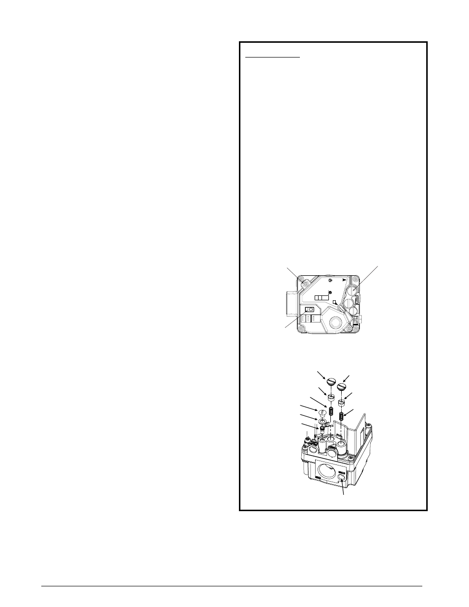
Figure 2. Two-Stage White Rodgers Gas valve
LOW REGULATOR COVER SCREW
(TWO STAGE ONLY)
REGULATOR ADJUST SCREW
REGULATOR SPRING
PILOT COVER SCREW
PILOT GASKET
PILOT ADJUST SCREW
REGULATOR SPRING
REGULATOR ADJUST SCREW
SINGLE STAGE AND TWO STAGE
HIGH REGULATOR COVER SCREW
MANIFOLD PRESSURE
TAP (OUTLET)
P/N - 624695
Model 36H64
IMPORTANT NOTE: When converting to LP/
Propane gas from natural gas, both springs from
the gas valve must be replaced by the white springs
included in the kit. The LP Propane springs for hIGh
and LOW fire are the same size, shape, and color.
1. Remove both regulator cover screws. See Figure 3.
2. Remove both regulator adjustment screws from the gas
valve (located beneath the cover screws).
3. Remove both Natural Gas regulator springs (color coded
silver / Plain) from the regulator sleeves.
4. Install both L.P. regulator springs (provided in the
conversion kit and color coded white) into the regulator
sleeves.
5. Replace the HIGH regulator adjustment screw and adjust
approximately 12 turns to the bottom stop.
6. Relace the LOW regulator adjustment screw and adjust
approximately 8 turns.
7. Check and adjust both regulator settings (High and Low
fire) to the firing rates listed in Table 3 for factory settings
below 2,000 ft elevation or for reduced firing rates based
on final high altitude calculations
Inlet
Pressure
Tap
Model 36H64
Manifold
Pressure
Tap (Outlet)
ON/OFF
Switch