Reznor R6GP Option - Installation - Bottom Power Entry User Manual
Page 5
5
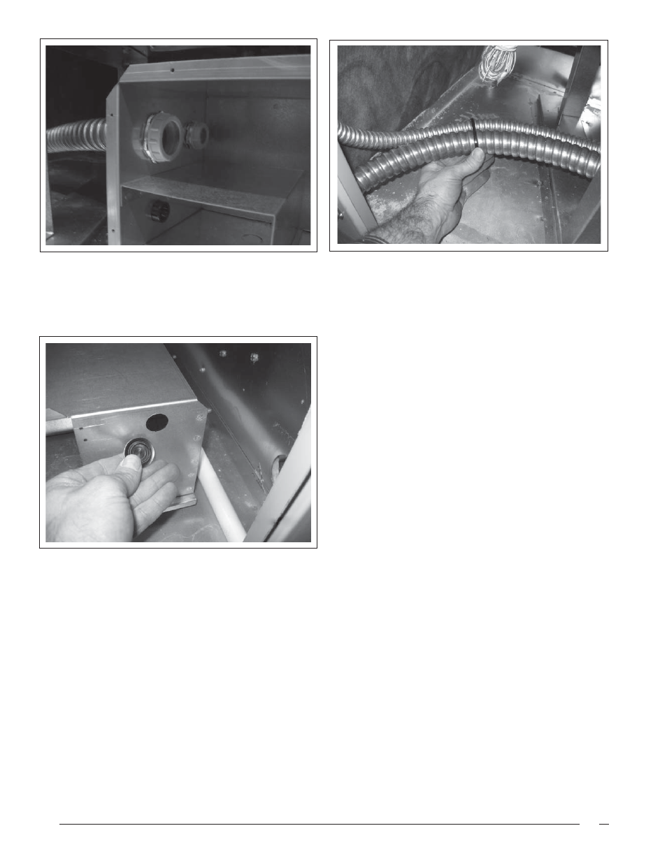
13. Install the threaded insulator bushings onto both
of the high voltage wiring conduits in the bottom
power entry box and in the unit control panel.
14. For Installations of equipment that do not include the
factory installed – convenience outlet option: Install
the provided, 7/8” plastic, button plug into the small
hole on the front face of the bottom power entry
box. (see Figure 12) On units that are equipped
with the convenience outlet, install the strain-relief
device instead of the button plug. (Field supplied:
two-screw or other applicable device.) For more
information, refer to the factory installed outlet
instructions.
Figure 8.
Figure 10.
Figure 9.
15. Holding the ¾” diameter conduit tight to the corner
of the compartment, use one of the supplied zip-
ties to secure the two FMC conduits together.
16. Install unit disconnect and conduit to connect
disconnect to the unit’s heat exchanger end panel.
Refer to the Unit’s Installation Instructions, Physical
Data Pages, for the recommended disconnect
mounting location and connection points. (See
Figures 14 & 18)
17. Bring the high voltage, unit power supply wiring
(and if applicable, 110V convenience outlet supply
wiring) into the right side of the bottom power entry
box for connections. Route wires from the bottom
power entry box, to the unit disconnect and then
to the unit HV inputs. Refer to the unit and other
installed accessory kits installation instructions for
details. (See Figure 18)
18. Bring the Low voltage, unit control wiring into the
bottom power entry box, under the low voltage
divider. Make connections in the bottom power
entry box, low voltage area – or – route wires/cable
through the star bushings installed in step 9 to the
unit low voltage connections through the base of
the unit control panel. (See Figure 18)
19. Using the remaining zip-ties, secure the FMC
conduits and low-voltage cable together. Ensure
that the wiring is secure and will not interfere with
the blower operation. Secure the bottom power box,
cover plate in place with the supplied screws.