Reznor PDH Option - Installation - Venting Instructions User Manual
Page 3
Form I-PDH-V, P/N 211409R2, Page 3
5. Vent System
Support
Support horizontal runs every six feet (1.8M). Support vertical runs of Category III
or Type “B” double-wall vent pipe in accordance with the requirements of the pipe
manufacturer. Support single-wall vertical pipe in accordance with accepted industry
practice. Do not rely on the heater for support of either horizontal or vertical vent pipe.
Use non-combustible supports on vent pipe.
Do not enclose vent pipe or place pipe closer than 6” (152mm) to combustible material.
On all Model Sizes, any length of single-wall vent pipe exposed to cold air or run
through an unheated area or an area with an ambient temperature of 45°F or less must
be insulated along its entire length with a minimum of 1/2” foil-faced fiberglass, 1-1/2#
density insulation.
Where extreme conditions are anticipated, install a means of condensate disposal.
The vent terminal pipe
must be double-wall (Type B) vent pipe. Heaters must be
equipped with a Reznor vent cap or equivalent. A different style vent cap could cause
nuisance problems or unsafe conditions. The vent cap must be the same size as the
vent pipe.
See
TABLE 3 and FIGURE 2 for requirements of a horizontal vent terminal. See FIG-
URE 3 for requirements of vertical vent termination.
4. Vent System Joints
and Sealing
Vent system joints depend on the type of pipe being used (See “Type of Vent Pipe”,
Requirement No. 1, page 2).
• If using single wall, 26-gauge or heavier galvanized pipe, secure slip-fit
connections using sheetmetal screws or rivets. Seal all joints and seams of single-
wall vent pipe inside the building with aluminum tape or silicone sealant.
• If using Category III vent pipe, follow the pipe manufacturer’s instructions for
joining pipe sections. When attaching Category III pipe to the venter outlet and
to the double-wall (Type B) vent terminal, make secure, sealed joints following a
procedure that best suits the style of Category III pipe being used.
• When using double-wall (Type B) vent pipe, follow the pipe manufacturer’s
instructions for joining pipe sections.
For joining double-wall pipe to the heater collar, single-wall pipe, and vent cap,
follow the illustrated instructions in the Addendum Section,
pages 5-7.
7. Condensation
8. Vent Terminal (Pipe
and Vent Cap -
See FIGURE 2 or
FIGURE 3.)
6. Clearance
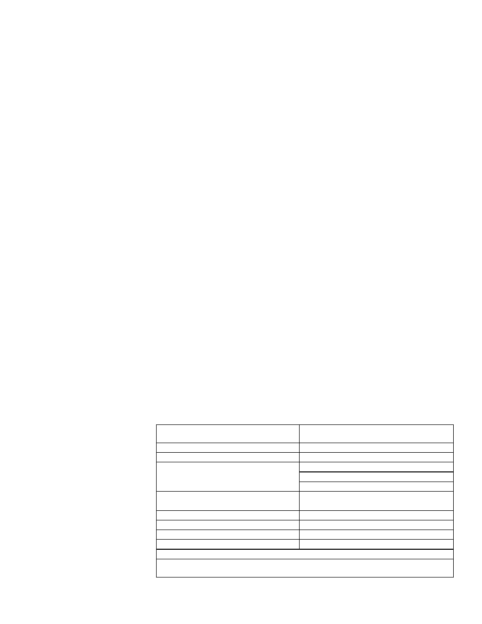
TABLE 3 - Horizontal
Vent Terminal
Clearances
Structure
Minimum Clearances for Vent Termination
Location (all directions unless specified)
Forced air inlet within 10 ft (3.1M)
3 ft (0.9M) above
Combustion air inlet of another appliance
6 ft (1.8M)
Door, window, or gravity air inlet
(any building opening)
4 ft (1.2M) horizontally
4 ft (1.2M) below
1 ft (305mm) above
Electric meter, gas meter*, and relief
equipment
U.S. - 4 ft (1.2M) horizontally
Canada - 6 ft (1.8M) horizontally)
Gas regulator *
3ft (0.9M) horizontally
Adjoining building or parapet
6 ft (1.8M)
Adjacent public walkways
7 ft (2.1M) above
Grade (ground level)
1 ft (0.9M) above**
*Do not terminate the vent directly above a gas meter or service regulator.
** Consider local snow depth conditions. The vent must be at least 6” (152mm) higher than
anticipated snow depth.
Maintain a minimum clearance of 6 inches (152mm) from the wall to the vent terminal
cap for stability under wind conditions.
Products of combustion can cause discoloration of some building finishes and dete-
rioration of masonry materials. Applying a clear silicone sealant that is normally used
to protect concrete driveways can protect masonry materials. If discoloration is an
esthetic problem, relocate the vent or install a vertical vent.
Horizontal Vent
Terminal