Reznor UDAP-CV with option AV6 Option - Installation - Common Vent User Manual
Page 6
Form I-UD-V-CV, P/N195677R5, Page 6
These instructions apply to the proper installation of a Model UDAP-CV in a
common vent application. The information provided is based on material pub-
lished in the National Fuel Gas Code and engineering calculations. The Model
UDAP-CV is a fan assisted (FAN) Category I heater. Instructions for the proper
installation of other appliances connected in common with the Model UDAP-
CV unit heater should be obtained from the manufacturer’s instructions or the
National Fuel Gas Code. In the case of conflicting instructions the most con-
servative instruction must be applied.
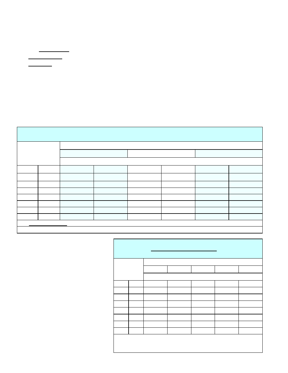
The vertical portion of the common vent must be Type B double-wall or a
masonry chimney lined with Type B double-wall pipe. Refer to
TABLE 4A to
determine the vent diameter required for the combined BTU/H input capacities
of all appliances to be connected and the height of the common vent portion of
the venting system. In
TABLE 4A, “FAN” refers to fan assisted appliances and
“
NAT” refers to appliances that rely solely on the natural buoyancy of the vent
gases for venting.
3.1 SECTION 2 - Model UDAP-CV Category I Common
Venting Instructions
If single-wall pipe is used in the
horizontal vent connector, refer to
TABLE 4B to determine the maximum
horizontal vent connector length
permitted.
If double-wall pipe is used in the
horizontal vent connector, refer to
TABLE 4C to determine the maximum
horizontal vent connector length
permitted. Two elbows may be used
in the horizontal vent connection with
a maximum rise of three feet (.9M).
NOTE: When two or more vent
connectors enter a common vent,
the smaller connector shall enter
at the highest level consistent with
available headroom or clearances to
combustible material.
3.0 SECTION 2 -
Requirements
and
Instructions
for Category
I Common
Venting of a
Model UDAP-
CV (cont’d)
T
ABLE 4A - Common Vent Capacity when a Category I Model UDAP-CV is Installed
with other Category I Appliance(s)*
Vertical Height
of Vent
Type B Double-Wall Common Vertical Vent
1
Diameter
5 inches
6 inches
7 inches
Maximum Combined Input Rating of the Appliances (mbh)
ft
M
FAN + FAN
FAN + NAT
FAN + FAN
FAN + NAT
FAN + FAN
FAN + NAT
6
1.8
NA
102
180
142
274
220
7
2.1
NA
108
188
149
286
231
8
2.4
147
113
196
156
298
242
10
3.0
170
123
213
170
321
263
15
4.6
187
143
248
199
374
309
20
6.1
212
159
275
222
417
345
30
9.1
241
182
315
257
480
401
* If a conflict in capacity occurs with other instructions, the more conservative capacity must be chosen.
1
This table may also be used for Type B double-wall lined masonry chimneys.
TABLE 4B - Maximum Horizontal Length of
Single-Wall Connector Pipe for
Model UDAP-CV* (Category I Common Vent)
Vertical
Height of
Vent
UDAP-CV Model Size
30
45
60
75
100
Diameter of Vent Connector (inches)
ft
M
4
4
4
4
5
6
1.8
0
0
2
3
3
7
2.1
2
2
2
3
3
8
2.4
3
3
3
3
3
10
3.0
3
4
4
4
4
15
4.6
3
4
5
5
6
20
6.1
3
4
5
5
6
30
9.1
3
4
5
5
6
* For the proper vent connector length and diameter of other appliances
connected in common with the Model UDAP-CV unit heater, refer to the
appliance manufacturer’s instructions or the National Fuel Gas Code.