Reznor UDAP-CV with option AV6 Option - Installation - Common Vent User Manual
Page 3
Form I-UD-V-CV, PN195677R5, Page 3
H
L
Type B Double-Wall
Vent Connector and
Vertical Vent Pipe
Model
UDAP-CV
FIGURE 1A
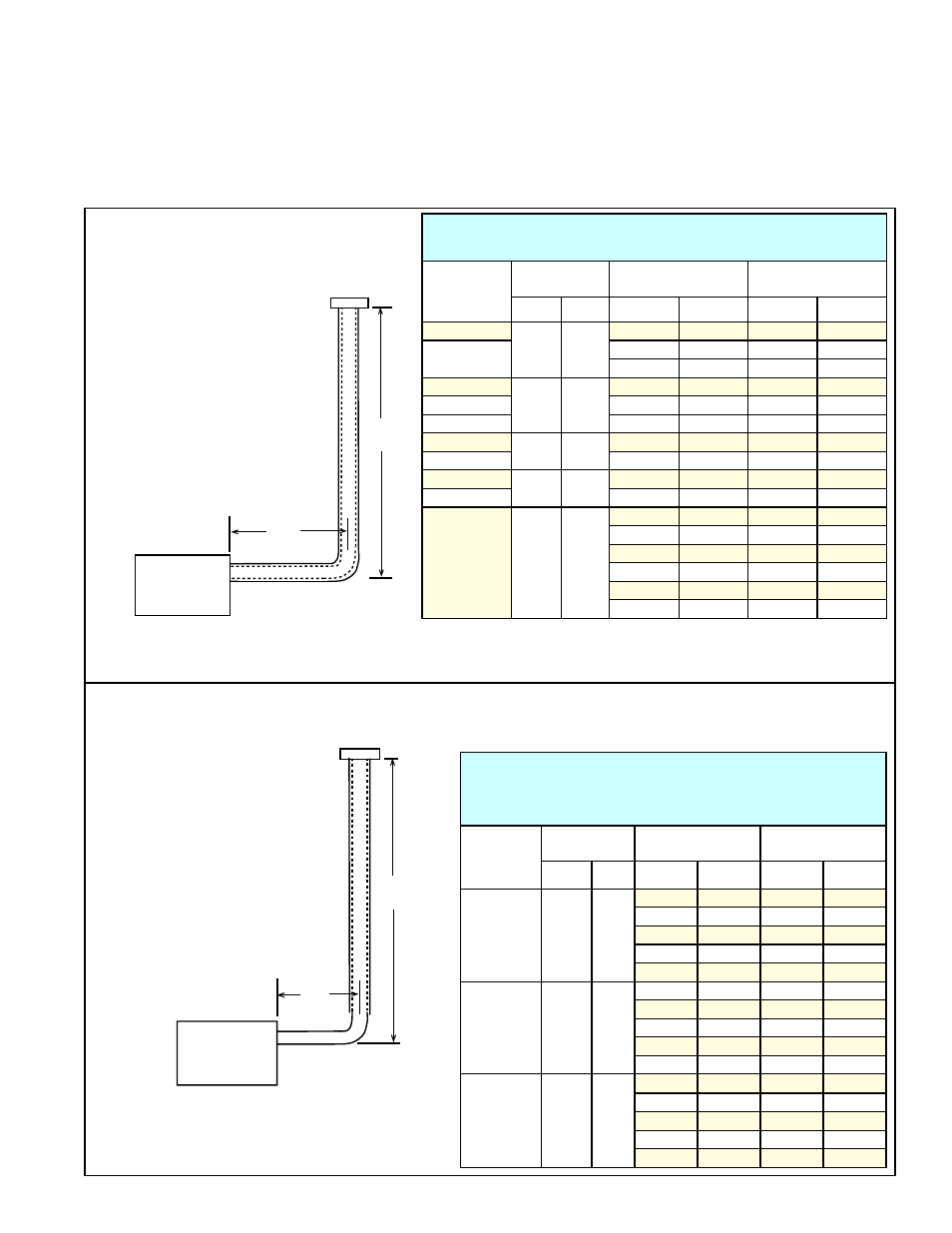
H = Vertical Height of Double-Wall Vent
L = Maximum Horizontal Double-Wall Vent Connector Length
FIGURE 1A and TABLE 1A - Vent
Lengths for Model UDAP-CV with
a Category I Vent using all Type B
Double-Wall Vent Pipe
2.2 SECTION 1 -
Vent Diameter
and Length
TABLE 1A - Vent Lengths of Category I Vent for
Model UDAP-CV Using All Double-Wall Vent Pipe
Model
UDAP-CV
Size
Vent
Diameter
H
L
inches mm
ft
M
ft
M
30
4
102
6
1.8
4
1.2
45, 60, 75
6
1.8
6
1.8
8
2.4
8
1.5
30
4
102
10
3.0
2
0.6
45
10
3.0
5
1.5
60, 75
10
3.0
10
3.0
30, 45
4
102
15
4.6
5
1.5
60, 75
15
4.6
15
4.6
30, 45
4
102
20
6.1
5
1.5
60, 75
20
6.1
20
6.1
100
5
127
6
1.8
6
1.8
8
2.4
8
2.4
10
3.0
10
3.0
15
4.6
15
4.6
20
6.1
20
6.1
30
9.1
30
9.1
FIGURE 1B and TABLE 1B - Vent Lengths for Model UDAP-CV 60, 75, or 100 with a
Category I Vent with a Single-Wall Vent Connector and a Type B Double-Wall Vertical Vent
Pipe
TABLE 1B - Vent Lengths of Category I Vent
with Single-Wall Connector to Double-Wall
Vent for Model UDAP-CV 60, 75, or 100
Model
UDAP-CV
Size
Vent
Diameter
H
L
inches mm
ft
M
ft
M
60
4
102
6
1.8
2
0.6
8
2.4
2
0.6
10
3
2
0.6
15
4.6
2
0.6
20
6.1
2
0.6
75
4
102
6
1.8
2
0.6
8
2.4
4
1.2
10
3.0
4
1.2
15
4.6
5
1.5
20
6.1
5
1.5
100
5
127
6
1.8
4
1.2
8
2.4
4
1.2
10
3.0
5
1.5
15
4.6
5
1.5
20
6.1
5
1.5
H
L
Double-Wall
Vertical Vent Pipe
Single Wall
Vent Connector
Model
UDAP-CV
FIGURE 1B
H = Vertical Height of Double-Wall Vent
L = Maximum Horizontal Single-Wall
Vent Connector Length
Vent diameter for Sizes 30, 45 60, and 75 is 4 inches (102mm).
Vent diameter for Size 100 is 5 inches (127mm).
Vent length requirements vary depending on size of heater and the type of
pipe used in the vent connector. If using a double-wall vent connector, refer to
FIGURE 1A and comply with vent lengths in TABLE 1A. If using a single-wall
vent connector (Sizes 60, 75, 100 only), refer to
FIGURE 1B and comply with
vent lengths in
TABLE 1B.