Red mini-mag side ssd module connectors, Red mini-mag side ssd module leds, Red dsmc media operation guide – RED DSMC MEDIA User Manual
Page 11
RED DSMC MEDIA OPERATION GUIDE
COPYRIGHT © 2014 RED.COM, INC
955-0047, REV-F | 11
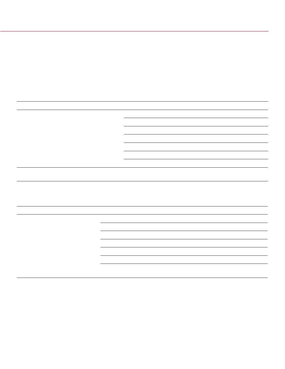
RED MINI-MAG SIDE SSD MODULE CONNECTORS
This section describes the connectors for all of the RED MINI-MAG modules.
Each RED MINI-MAG modules mounts to the left side of the DSMC BRAIN. The rear face of this module features
a slot for inserting a RED MINI-MAG.
WARNING: DO NOT attempt to insert any media type except for the RED MINI-MAG, or any foreign objects, into
the SSD slot, as that may damage the RED MINI-MAG module or DSMC system.
The EVF/LCD connector on the front face of the RED MINI-MAG module provides digital vid-
eo, communications, and power interconnection between the DSMC and a RED EVF or RED LCD.
Due to the requirement for absolute data integrity, the pinout of the EVF/LCD connector is not published.
CONNECTOR
DESCRIPTION
COMPATIBLE PARTS
PART NUMBERS
EVF/LCD connector
VIEWFINDER output
LCD/EVF CABLE (RIGHT-TO-RIGHT) 7"
790-0158
LCD/EVF CABLE (RIGHT-TO-RIGHT) 12"
790-0162
LCD/EVF CABLE (RIGHT-TO-RIGHT) 18"
790-0448
LCD/EVF CABLE (RIGHT-TO-RIGHT) 32"
790-0449
LCD/EVF CABLE (RIGHT-TO-STRAIGHT) 24" 790-0451
LCD CABLE 6'
790-0055
LCD CABLE 10'
790-0056
RED MINI-MAG slot
Slot for inserting a
RED MINI-MAG
RED MINI-MAG
750-0053
RED MINI-MAG SIDE SSD MODULE LEDS
This section describes the LED for all of the RED MINI-MAG modules.
LED
COLOR/FLASHING
DESCRIPTION
Media Indicator LED
Off
No media present
Green
Ready to record
Red
Recording
Red slow flashing
Recording; 25% media left
Red fast flashing
Recording; 5% media left
Amber
Finalizing
Amber flashing
Accessing media (for example,
when formatting)