Trig ty91 mounting requirements, Audio panel mounting rack installation, Cable harness wiring – PS Engineering PAR200 User Manual
Page 9: Noise, Ty91, Mounting requirements, Udio, Anel, Ounting, Nstallation
PS Engineering Inc. ®
PAR200 Audio Selector Panel, COM radio Controller and Intercom System
Installation and Operator’s Manual
200-228-0000
Page 2-2
Rev. 4, Dec. 2013
2.3.3
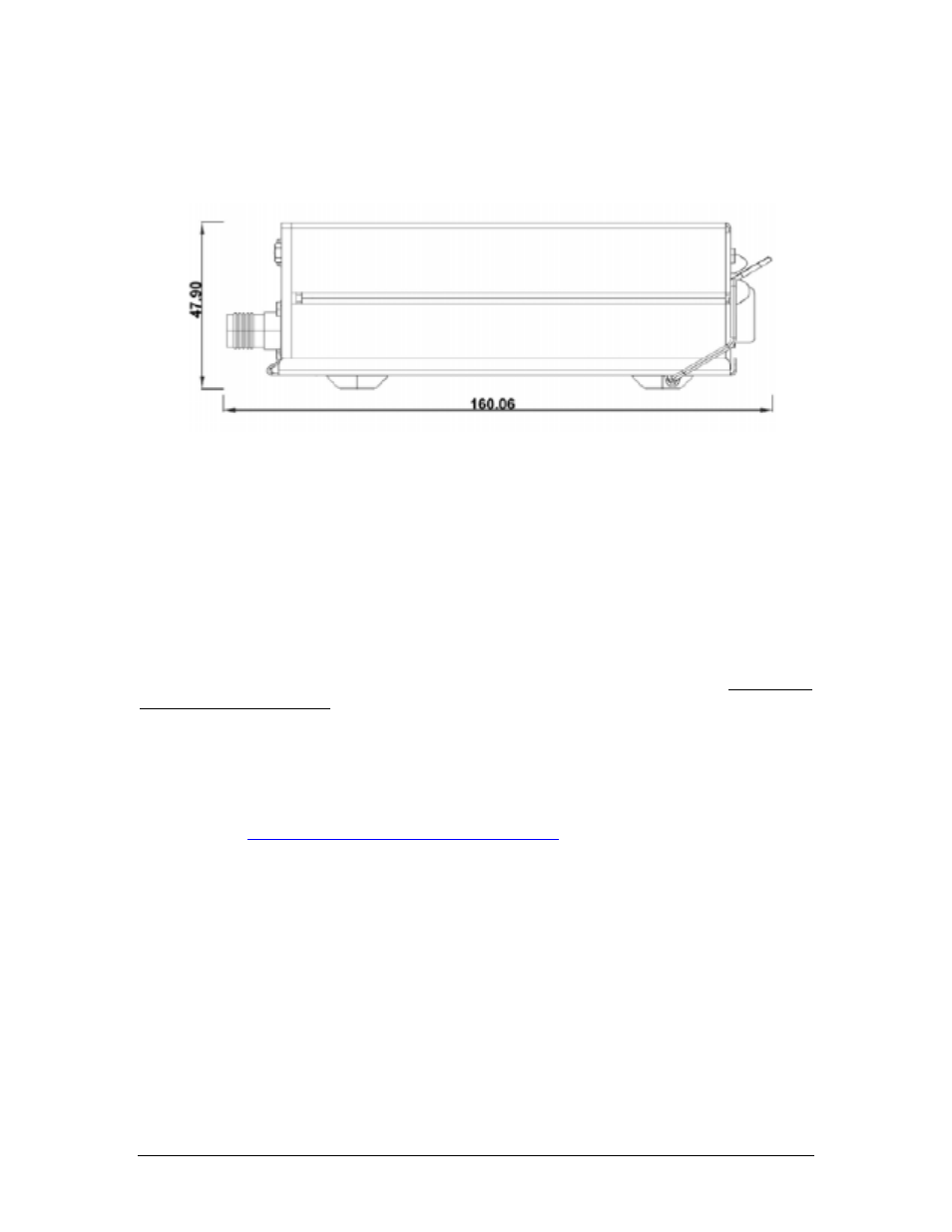
Trig TY91 mounting requirements
The TY91 remote VHF Communications radio is mounted to the aircraft structure with 4 ea #6-32 (not
supplied) screws through the mounting flange. Guidance can be found in AC 43.13-2B, Chapter 2.
Figure 2-1 TY91 VHF Transceiver (Remote Mount)
2.3.4
Audio Panel Mounting Rack Installation
Remove the audio panel from the mounting tray by unscrewing the 3/32" hex-head screw that is in the
center of the unit. Use caution to avoid hitting the photo-detector lens. Carefully slide the unit free of the
tray. Set the unit aside in a safe location until needed. Install the tray using six clip nuts (475-630-0002),
and six FHP 6-32 x ½" screws (475-632-0012). The audio selector panel must be supported at front and
rear of the mounting tray.
2.4 Cable Harness Wiring
Referring to the appropriate Appendix, assemble a wiring harness as required for the installation. All
wires must be MIL-SPEC in accordance with current regulations. Two- and three-conductor shielded wire
must be used where indicated, and be MIL-C-27500 or equivalent specification. Proper stripping, shield-
ing and soldering technique must be used at all times. It is imperative that correct wire be used.
Refer to FAA Advisory Circular 43.13-2B for more information. Failure to use correct techniques may
result in improper operation, electrical noise or unit failure. Damage caused by improper installation will
void the PS Engineering warranty.
Custom factory wiring harnesses can be purchased from PS Engineering, call 865-988-9800 for details or
visit our website
and click on Work Sheet for the appro-
priate product.
2.4.1
Noise
Due to the variety and the high power of radio equipment often found in today's general aviation aircraft,
there is a potential for both radiated and conducted noise interference.
The PAR200 power supply is specifically designed to reduce conducted electrical noise on the aircraft
power bus by at least 50dB. Although this is a large amount of attenuation, it may not eliminate all noise,
particularly if the amplitude of noise is very high. There must be at least 13.8 VDC present at the connec-
tor, J2 pins 8 & 9, of the PAR200 for the power supply to work in its designed regulation. Otherwise, it
cannot adequately attenuate power line noise. Shielding can reduce or prevent radiated noise (i.e., beacon,
electric gyros, switching power supplies, etc.) However, installation combinations can occur where inter-
ference is possible. The PAR200 was designed in a RFI hardened chassis and has internal Electromag-
netic Interference (EMI) filters on all inputs and outputs.