Unswitched inputs, Intercom wiring, Music inputs – PS Engineering PAR200 User Manual
Page 15: Nswitched inputs, Ntercom wiring, Usic, Nputs
PS Engineering Inc. ®
PAR200 Audio Selector Panel, COM radio Controller and Intercom System
Installation and Operator’s Manual
200-228-0000
Page 2-8
Rev. 4, Dec. 2013
If an external dimmer control is not used, a constant back light illumination can be established for night-
time viewing. Pin 6 or 7 (depending on system voltage) must be tied to power (J2, pin 8 or 9) for the back
lighting system to work. The photocell mounted in the unit face will automatically adjust the intensity of
the push-button annunciation green LEDs.
2.6.5
Unswitched inputs
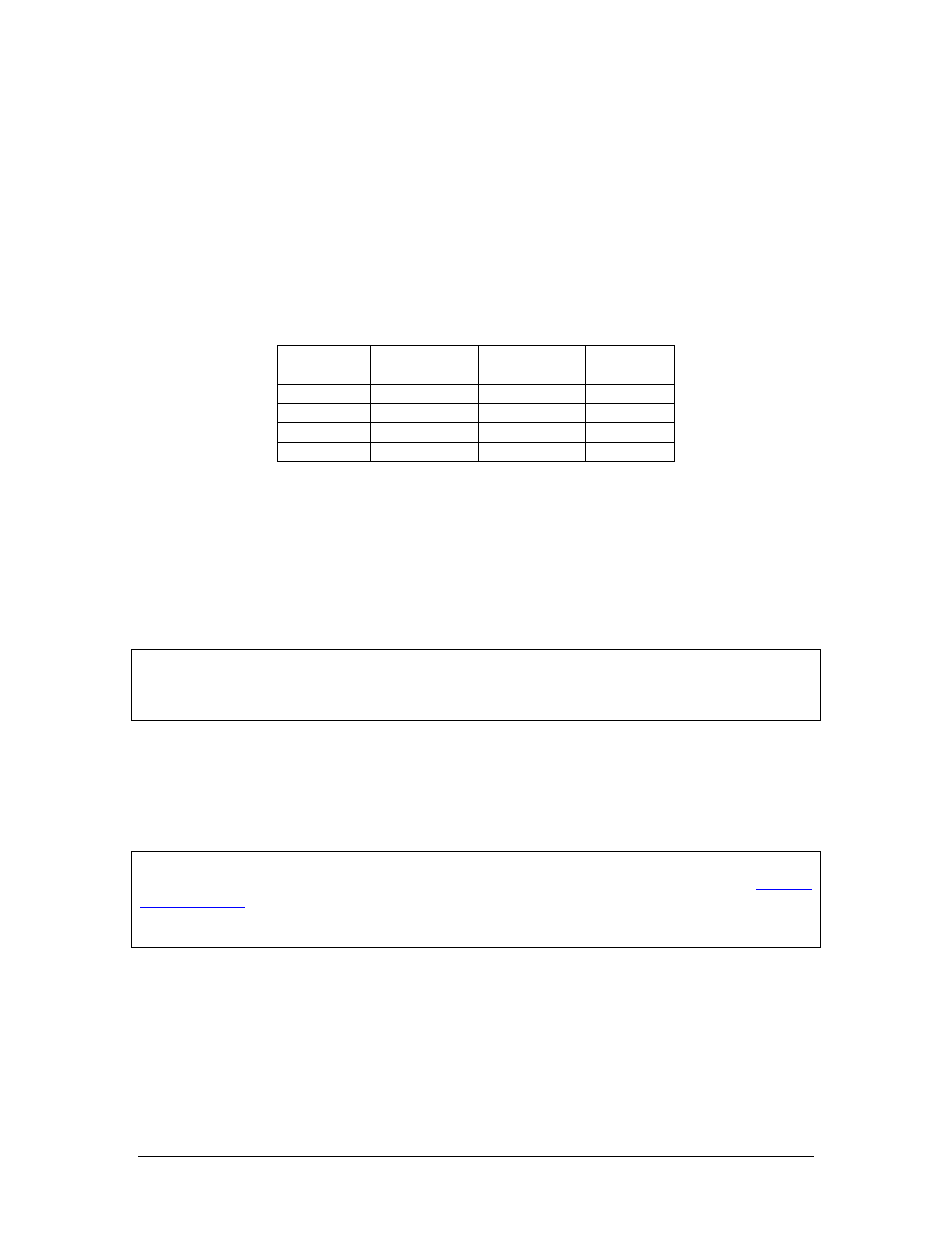
J1, pins 31, 29 and J2 pin 15 are unswitched, unmuted (by transmitter keying), inputs # 1, 3 and 4, re-
spectively. These inputs are presented to the pilot and copilot regardless of the audio configuration, and
will mute the entertainment inputs based on the mode. These 510 Ω inputs can be used for altimeter DH
audio, GPS waypoint audio, autopilot disconnect tones, or any other critical audio signal. Unswitched #1
is always presented to the crew headphones, and is available to the pilot in fail-safe (off) mode.
Unswitched
Input
Hear in
Fail Safe
Hear in
Crew Headset
Gain
1
Yes
Yes
1:1(fixed)
2
No
Yes
1:1(fixed)
3
No
Yes
Adjustable
4
No
Yes
1:1(fixed)
Table 2-5 Unswitched input table
J1, pins 31, 29 and J2 pin 15 are unswitched, unmuted inputs # 1, 3 and 4, respectively. These inputs are
presented to the pilot and copilot regardless of the audio configuration, and will always mute the enter-
tainment inputs. These 510Ω inputs can be used for altimeter DH audio, GPS waypoint audio, autopilot
disconnect tones, or any other critical audio signal.
The audio low for unswitched #4 (J2, pin 15) should be connected to a convenient audio low. However,
this should NOT be connected to Music Low.
Unswitched #1 is presented to the pilot headphone in fail-safe (off) mode.
NOTE
Inputs 1, 2 and 4 are fixed (1:1), and any audio level adjustments must be made at the input source. Unswitched #3
has a variable adjustment control located on the bottom side of the unit. This control allows you to control the volume
level of that unswitched input from 50% to 200% of the input level. Refer to Adjustments section.
2.7 Intercom wiring
See Appendix C and D for intercom connection configurations. It is critical to the proper operation of this
system to have this connector wiring made in accordance with these diagrams. Use 2- and 3-conductor,
MIL-spec cable as shown. Connect the shields at the audio panel end only, and tie to the audio low inputs
as shown.
NOTE
The system harness can be custom made by PS Engineering, Inc. Simply call the factory or
to obtain a wire harness work sheet. The harness will be made to your specifications and
fully functionally tested. Harness can be ordered with jack, or without the intercom jacks installed, for
easier wire routing through the aircraft.
2.7.1
Music Inputs
The PAR200 has two INDEPENDENT inputs wired into the rear connectors, in addition to the Blue-
tooth® music streaming (which is presented as Music 1). Music input number 1 is J2 pins 23 (left chan-
nel) and 24 (right channel), with respect to pin 25, and Music number 2 is connected to 26 (left channel),
27 (right channel), with respect to 28.
Music #1 is available to the pilot and copilot positions, only, in normal configuration. Music 1 can be hear
by all aircraft occupants, if Music 1 all headsets is activated. See §2.7.1.1