Communications antenna installation notes, Antenna location, Ty91(l) adjustments – PS Engineering PAR200 User Manual
Page 20: Ommunications, Ntenna, Nstallation, Otes, Ocation, Ty91, Djustments
PS Engineering Inc. ®
PAR200 Audio Selector Panel, COM radio Controller and Intercom System
Installation and Operator’s Manual
200-228-0000
Page 2-13
Rev. 4, Dec. 2013
2.12 Communications Antenna Installation Notes
2.12.1 Antenna Location
For best results while in Split Mode, we recommend that the one VHF communications antenna is located
on top of the aircraft while the other communications antenna is installed on the bottom. Any antenna
relocation must be accomplished in accordance with AC 43.13-2B, aircraft manufacturers’ recommenda-
tions, and other FAA-approved technical data.
WARNING
It is probable that radio interference will occur in the split mode when the frequencies of the two air-
craft radios are adjacent, and/or the antennas are physically close together. PS Engineering makes
no expressed or implied warranties regarding the suitability of the PAR200 in Split Mode.
2.13 TY91(L) Adjustments
2.13.1.1 TY91(L) Sidetone Level
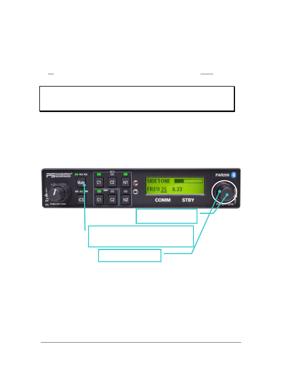
The radio transmit sidetone level is adjustable via the PAR200.
Push and hold the right hand knob until the volume screen appears. Then hold the
“MUTE” button on the left side until a sidetone level adjustment screen appears. Turn the
small knob to increase or decrease the sidetone level from the TY91(L).
2.13.1.2 Radio Frequency spacing, 25 kHz or 8.33 kHz
Push and hold the right hand knob until the volume screen appears. Then hold the
“MUTE” button on the left side until a sidetone level/channel spacing screen appears.
Turn the large knob to select either 25 kHz spacing or 8.33 kHz spacing.
1. Push/hold for >1 second.
2. After the volume screen appears, hold Mute until
SIDETONE screen appears
3. Adjust sidetone level