6 2.8.7 switched power to driver control panel, Fuel pump, Notice – Proheat A4 User Manual
Page 21
PROHEAT AIR A2/A4 INSTALLATION MANUAL
2-11
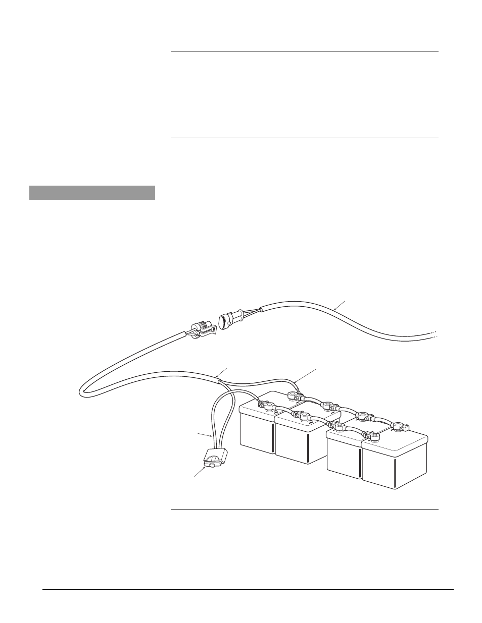
FUSE
RED (+)
POSITIVE
BLACK (-) NEGATIVE
FUSE HOLDER HARNESS
POWER SUPPY HARNESS
Figure 15. 24V DC Connections.
2.8.6
2.8.7
Switched Power to Driver Control Panel
The Driver Control Panel can determine if the vehicle is running or not by
monitoring the switched power coming from the ignition. By connecting this
cable, longer run times for supplemental heat is possible.
Connect the two pin connector to the DCP and feed the wire to an ignition
switched source. Connect both the Green and Yellow wires to a source that
goes HIGH when the ignition is ON.
Fuel Pump
The fuel pump is highly regulated and receives power and signal from the
controller located inside the heater.
Starting at the fuel pump, connect the Yellow/Green harness to the fuel
pump connector.
Route the wiring harness back to the heater and connect to the
corresponding connector at the heater main harness.
Bundle extra wire and secure out of the way with cable ties - DO NOT cut or
shorten the wire unless necessary.
NOTICE
It is possible to use one wire loom
for both fuel line and wiring harness.