5 2.8.4 main power to heater, Notice – Proheat A4 User Manual
Page 20
PROHEAT AIR A2/A4 INSTALLATION MANUAL
2-10
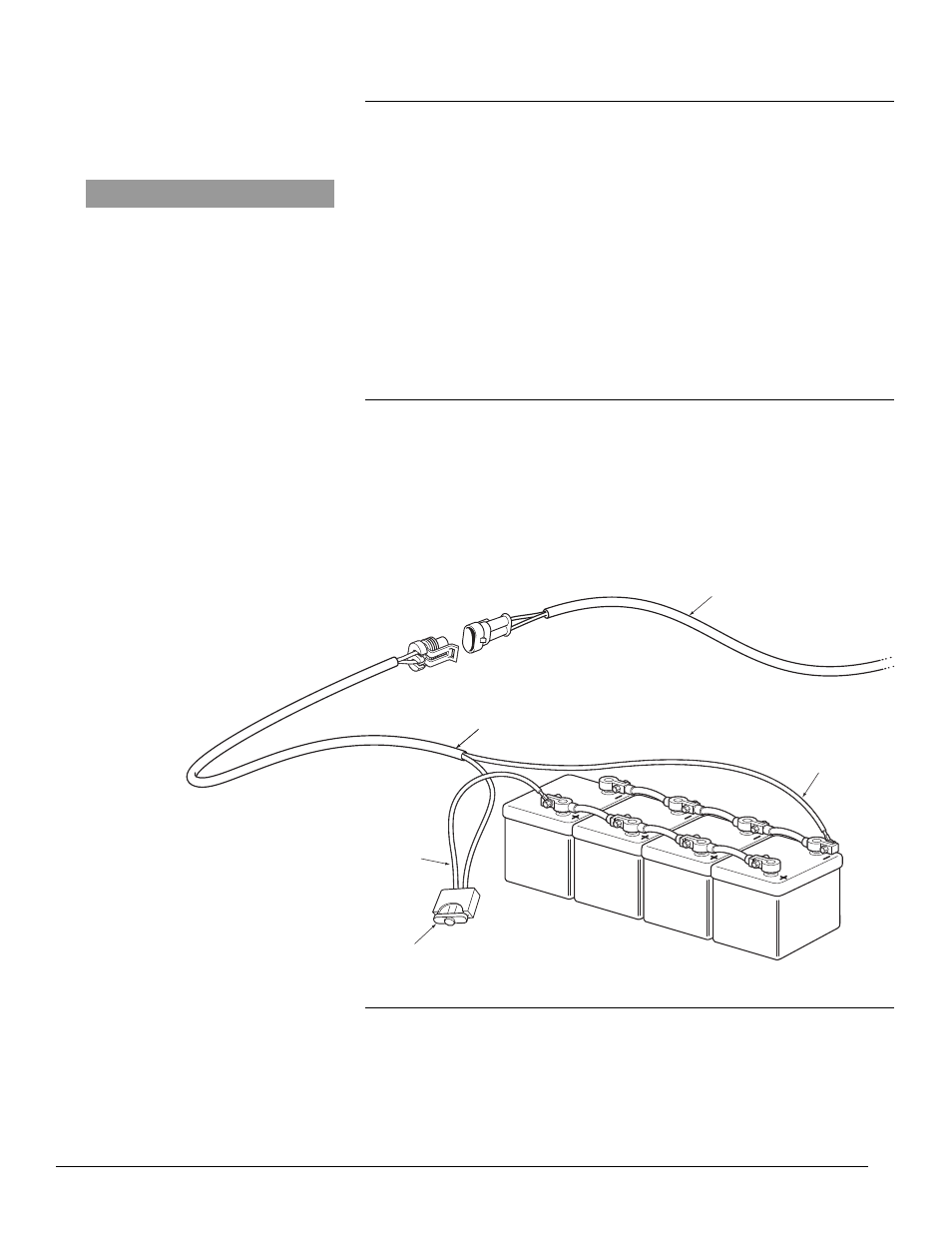
FUSE HOLDER HARNESS
POWER SUPPY HARNESS
FUSE
RED (+)
POSITIVE
BLACK (-) NEGATIVE
Figure 14. 12V DC Connections.
2.8.5
2.8.4
Main Power to Heater
The main power harness consists of two cables each with its own fuse to protect
both the heater and the wire harness from damage due to short circuits.
• Remove fuses from fuse holders
• Connect fuse holder harness to battery terminals observing correct polarity
and battery terminal
• Connect fuse holder harness to main power harness
• Route main power harness from the battery box to the heater and connect
• Bundle and secure excess wire out of the way
• Protect any exposed wire harness with wire loom
• Do not install fuses until the heater is completely installed and all
connections are tested
Power and Signal from Heater to Driver Control Panel
Power is supplied from the heater to the Driver Control Panel (DCP). Control
signals such as heater start or temperature settings are sent to the heater.
Information such as current temperature, heater status and diagnostic
information is sent from the heater to the DCP for display.
Connect the round connector from the DCP to the cable harness. Starting at
the DCP mounting location, feed the wire back through to the heater and
connect to the heater main harness.
NOTICE
Ensure the battery terminals are
clean and free of corrosion.