8 wiring & electrical connections, General considerations, Electrical connections – Proheat A4 User Manual
Page 18: 1 2.8.2 warning, Caution
PROHEAT AIR A2/A4 INSTALLATION MANUAL
2-8
2.8
WIRING & ELECTRICAL
CONNECTIONS
The Proheat Air heater is available in 12 or 24 volt DC models and work with
negative ground electrical systems only.
General Considerations
• All wire harnesses come complete with connectors and should not require
alteration.
• If making new connections, they must be crimped and soldered using rosin
core, not acid core solder.
• Ensure the vehicle batteries are in good condition and that connections are
clean and tight.
• Do not kink or abrade wires when routing.
• Use wire loom to protect cables when required.
• Use grommets whenever passing cable through a metal surface.
• Ensure wires are well secured and supported.
• Wires should be secured within 4" of all connections.
• All wires must have sufficient slack to prevent strain during vehicle operation.
Electrical Connections
• Main power to heater
• Power and signal from heater to Driver Control Panel (DCP)
- Pin 1 Yellow wire Key + DCP Backlight continuous on
- Pin 2 Green wire Key + Run Mode. When key on heater is in continuous
run. Key off heater is in Pre-Programmed Run Time (default 30 min)
- Or Permanent Override to Continuous Run Heat Mode
- Pin 2 Green wire to a continuous battery positive source. Heater will run
until manually turned off.
• Switched power to Driver Control Panel
• Power from heater to fuel pump
• External temperature Sensor (optional)
2.8.1
2.8.2
WARNING
DO NOT use on a positive ground
vehicle.
CAUTION
If repair to the vehicle requires
welding, disconnect the heater
power at the heater.
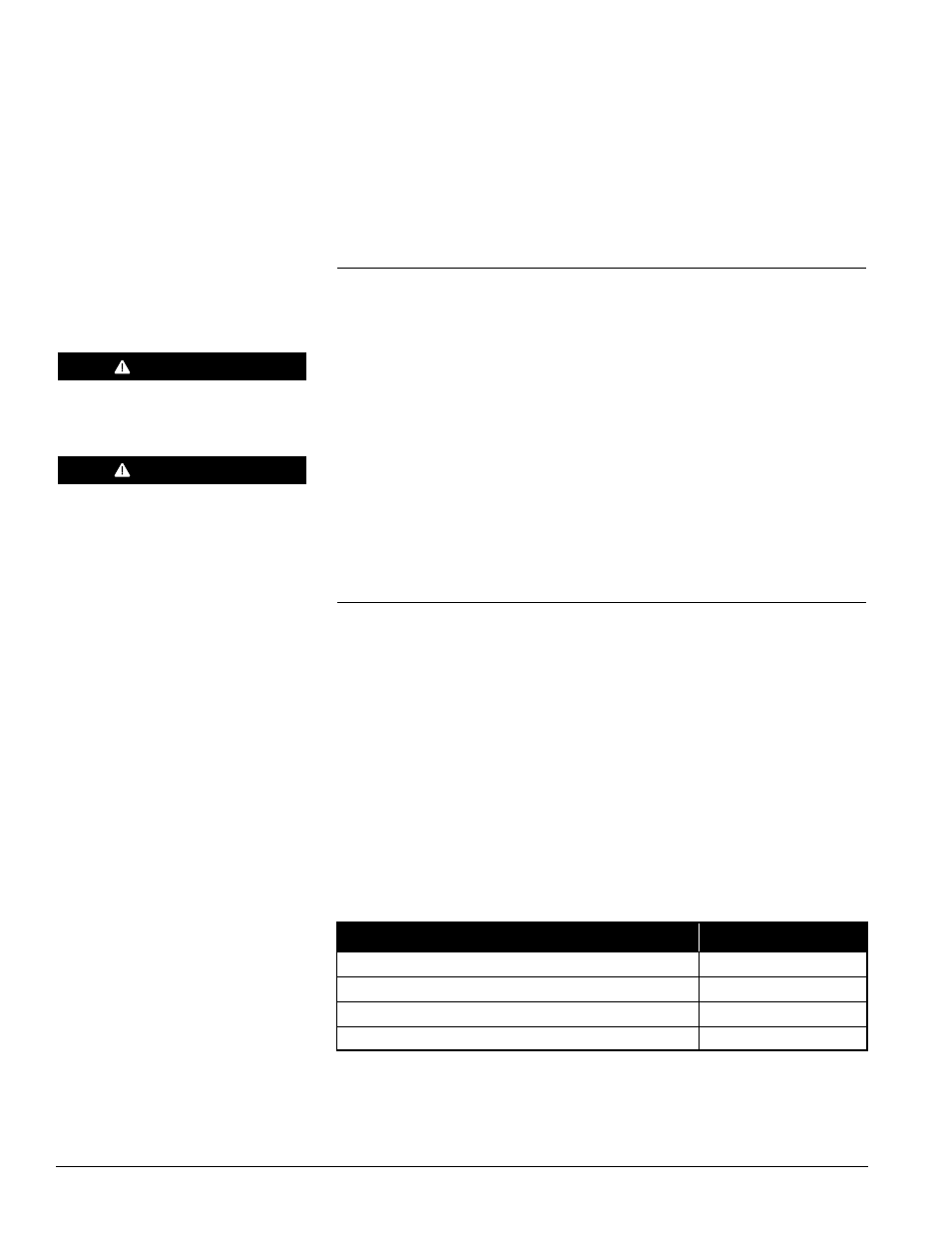
HARNESS
LENGTH
Main Power Heater to Battery and Fuse Holder
15 feet
Heater to Fuel Pump
19.7 feet
Heater to Driver Control Panel
15 feet
Driver Control Panel to Ignition
15 feet